Floating solar chimney

a solar chimney and solar energy technology, applied in the field of solar chimneys, can solve the problems of limited height of solar chimneys and high manufacturing costs, and achieve the effect of reducing the total cost of the overall power system and reducing the construction cos

Inactive Publication Date: 2010-06-15
PAPAGEORGIOU CHRISTOS
View PDF7 Cites 18 Cited by
  • Summary
  • Abstract
  • Description
  • Claims
  • Application Information

AI Technical Summary

Benefits of technology

[0007]The present invention eliminates the above-mentioned disadvantages by increasing, for a given power output, the height of the solar chimney, and decreasing their construction cost as well as the area of the solar collectors, and thereby decreasing the total cost of the overall power system for generating electricity.
[0008]This is achieved by constructing the solar chimney with a double wall formed from durable elastic for balloons or airships, filled with gas He (or other non-flammable light gas) that makes the chimneys lighter than air. The lighter-than-air floating solar chimney can have much bigger height than the conventional solar chimney formed from reinforced concrete, while simultaneously its costs remain considerably lower than the cost of a conventional chimney from reinforced concrete.
[0009]The construction of a floating, lighter-than-air chimney is implemented taking into consideration that the solar chimney is used exclusively for the up-drafting of warm air. Thus solar chimney stresses arise from the exterior winds and the Bernoulli pressure from the internal stream of warm air. An advantageous, simple and inexpensive construction can face these stresses effectively. The modern plastic and composite materials that are used for airships or balloons can be used for such a construction, combining light weight and high strength in the face of extreme stresses, with extended life under extreme exterior conditions.

Problems solved by technology

This has the following consequences:High manufacturing cost; andLimited height of the solar chimneys due to technological restrictions from the construction materials and from exterior limitations (e.g., earthquakes).

Method used


Image

  • Floating solar chimney
  • Floating solar chimney
  • Floating solar chimney

Examples


Embodiment Construction

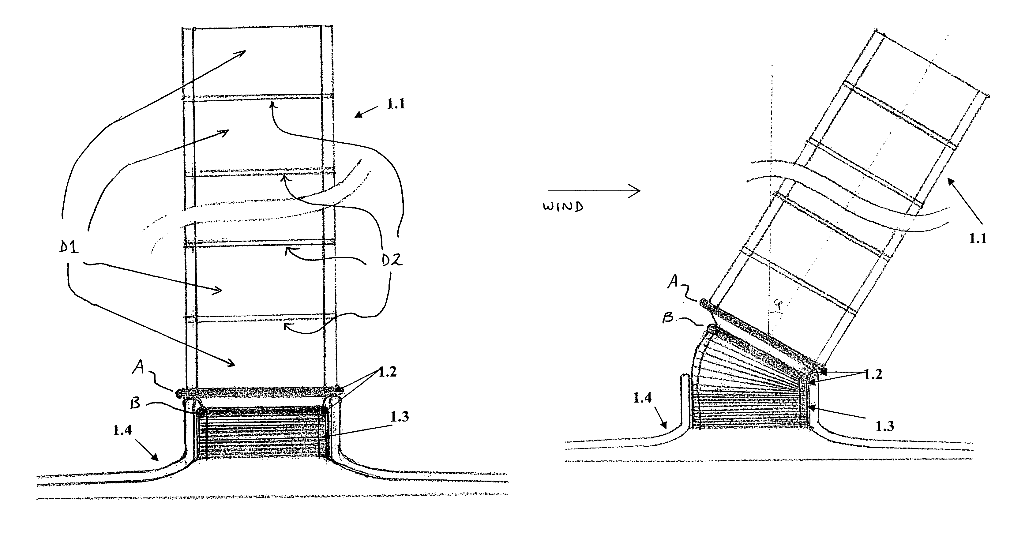
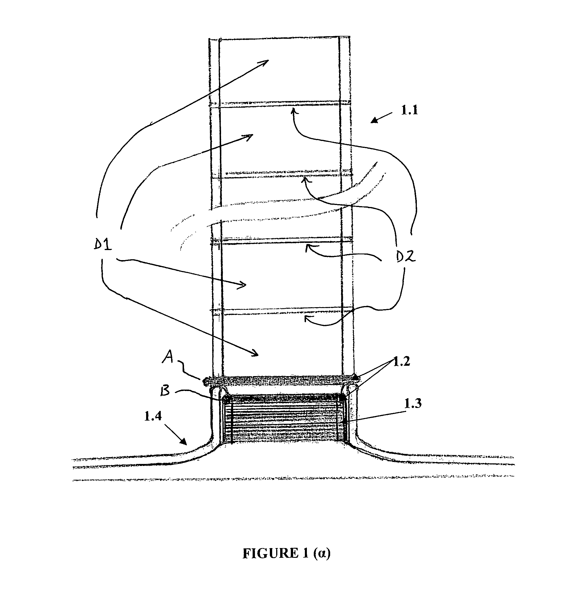
[0022]The floating solar chimney according to the present invention is based (anchored) on the seat (1.4) as shown in FIG. 1a: [0023]The Main Chimney (1.1) has a double wall filled with lighter-than-air inflammable gas that creates the necessary buoyancy. This lifting force dictates the main chimney to take, without exterior winds, a vertical position.[0024]The Heavy Mobile Base (1.2), also called the Heavy Base, by which the main chimney is suspended, has a total weight that is greater than the force represented by the total buoyancy of the main chimney. This dictates, in the absence of exterior winds, the heavy mobile base to sit on the seat (1.4) of the chimney.[0025]The folding lower part of the chimney (1.3) is inside the upper part of the seat (1.4) in the absence of exterior winds.

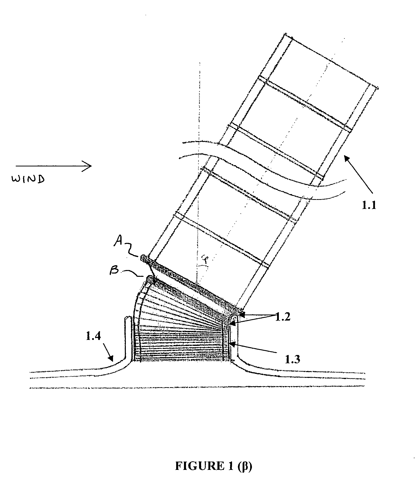
[0026]If exterior winds appear, the main chimney (1.1) declines to a balance angle. The heavy base (1.2) supported in the edges of the seat (1.4) assumes a corresponding declined position, and the f...


PUM


Abstract

A floating solar chimney includes several parts, e.g., the Main Chimney, the Heavy Base, and the Folding Lower Part. The main chimney includes cylindrical balloon rings full of non flammable light gas. The cylindrical balloon rings are tied with the help of supporting rings so that together they form one or more compact units of the main chimney. The compact parts of the main chimney are fastened on the heavy base. The successive compact parts are separated by separating rings filled with environmental air that can go in and out of the separating rings, so that the dynamic independence of the successive compact parts is ensured. The main chimney, which can float, is configured to sit on a chimney seat, and is connected to the heavy base. The lower part of the heavy base is fastened to the folding lower part. The air can enter and come out freely from the rings of folding lower part in order to enable the floating solar chimney to achieve any suitable decline as dictated by the exterior winds.

Description

FIELD OF THE INVENTION[0001]The present invention relates to solar chimney that can collaborate with solar collectors and wind turbo generators and form electric power stations working by solar power.BACKGROUND INFORMATION[0002]Such conventional electric power systems using solar energy, with the method of solar collectors and solar chimneys, are based on the principle of solar heating of air in a solar collector of a large area. The warm air rises, through a collaborating solar chimney that is based on the center of the collector, to upper layers of atmosphere, acquiring up-draft speed, due to the height of the solar chimneys. Part of the thermo mechanical energy of this up-drafting current of warm air, via a system of the wind turbines and generators in the base of the solar chimney, transforms into electric energy. The solar chimney in this conventional system is typically manufactured by reinforced concrete. This has the following consequences:[0003]High manufacturing cost; and[...

Claims


Application Information

Patent Timeline
Patent Type & Authority Patents(United States)
IPC IPC(8): F24J2/46F03D1/04F03G6/04
CPCF03D1/04F03G6/045F05B2240/131Y02E10/72F05B2240/93Y02E10/465F05B2240/922Y02E10/46
Inventor PAPAGEORGIOU, CHRISTOS
Owner PAPAGEORGIOU CHRISTOS
Why Eureka
Try Eureka