Apparatus and method for continuous particle separation

a particle and apparatus technology, applied in the field of microfluidic methods and devices for the separation of particles according to size, can solve the problems of limiting resolution, limiting resolution, and low diffusion coefficient, and achieve the effect of low reynolds number

Active Publication Date: 2010-06-15
THE TRUSTEES FOR PRINCETON UNIV
View PDF7 Cites 109 Cited by
  • Summary
  • Abstract
  • Description
  • Claims
  • Application Information

AI Technical Summary

Problems solved by technology

This multipath zone broadening (Eddy diffusion) is a major factor limiting resolution.
Other methods for separation according to size, including gel electrophoresis, field-flow fractionation, also involve stochastic processes, which may limit their resolution.
However, because the diffusion coefficient is low for large molecules, the asymmetric obstacle arrays are slow, with running times of typically more than 2 hours.
However, these devices generally require features sizes comparable to or smaller than the molecules being fractionated.
The need for small feature size may have the following detrimental effects: (i) the devices cannot fractionate small molecules such as proteins, (ii) the devices may have very low throughput, and thus are not useful sample preparation tools, (iii) the devices can only analyze very small volume of samples, and therefore usually require concentrated samples or expensive equipment for sample detection, and (iv) manufacturing the devices require state-of-the-art fabrication techniques, and thus high cost.
However, they typically require additional labels.
In general, these processes are complex, involve fluorescent labeling, yield incomplete fractionation, clog easily, or introduce bias to the data.

Method used


Image

  • Apparatus and method for continuous particle separation
  • Apparatus and method for continuous particle separation
  • Apparatus and method for continuous particle separation

Examples


example 1

Fractionating Device

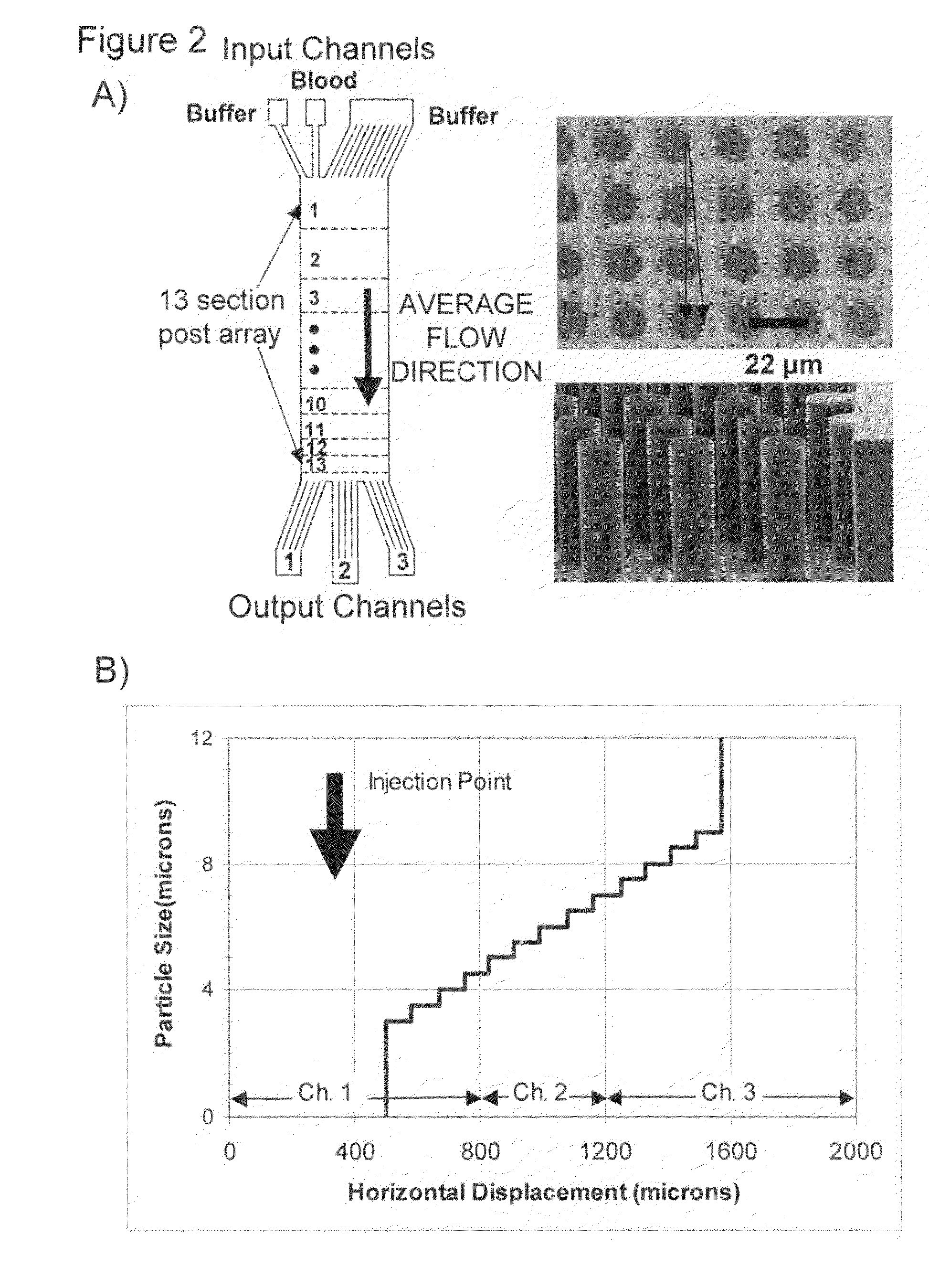
[0057]An analytical fractionating device was fabricated to separate white blood cells from red blood cells and plasma, and to fractionate the white blood cells according to size. The device had a narrow throat width of 50 μm, and was designed to work with 10 μl of blood or less, rather than large volumes. The device is illustrated in FIG. 2. As the main design concern was to create a high dispersion with a range in the sizes of white blood cells of 5 to 10 μm, the device was not designed to remove smaller objects, such as platelets, which have a diameter on the order of 1 μm. Therefore, the required dynamic range was less than 4, and only a single chirped ε region with a constant gap G was required. A schematic of the device is illustrated in FIG. 2A.

[0058]Whole blood and a running buffer were introduced into separate channels at the top of the device, and vertical laminar flow was maintained throughout the device. The active region of the device had 13 consecuti...

example 2

Preparative Device

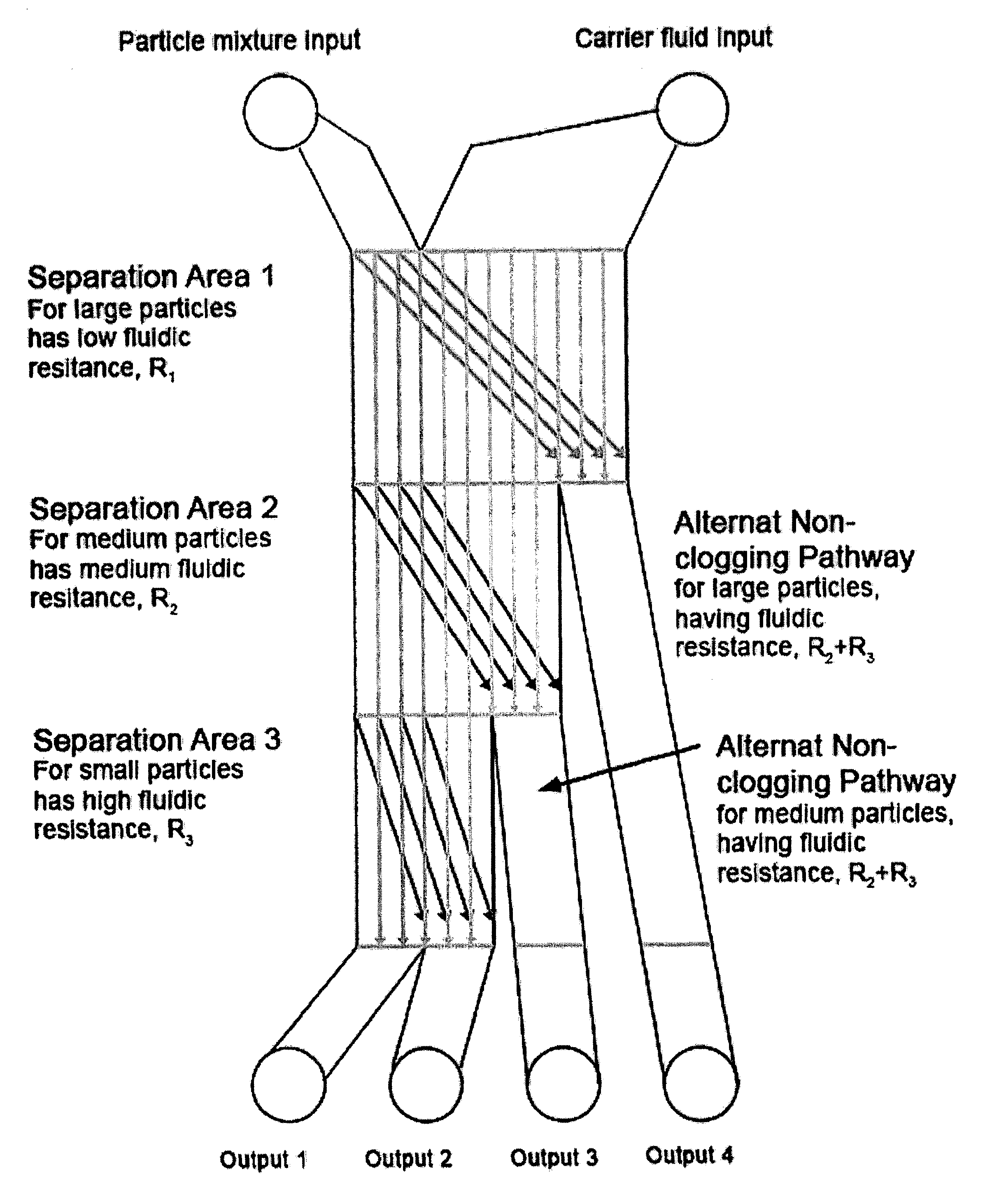
[0066]A preparative device was designed and fabricated for the isolation of undiluted blood plasma from whole blood for further study. The device was fabricated with a wide throat width of 500 μm, which was one-half of the 1 mm wide active area. This allowed the preparation of larger volumes and higher flow rates, such that flow rates of at least 1 μl / min were possible, as illustrated in FIG. 6. Because the device was required to remove both large 10 to 20 μm diameter white blood cells as well as small platelets, only the high dynamic range of a cascade device would work without clogging. In the fabricated device, the cascade had three different regions with three different gap sizes. As this particular application required only the production of a substantially cell-free plasma, the individual fractionations produced in each of the regions are not maintained. Instead, all components larger than 1.5 μm were combined in the balanced serpentine region on the side of ...


PUM

PropertyMeasurementUnit
sizeaaaaaaaaaa
sizeaaaaaaaaaa
sizeaaaaaaaaaa

Abstract

The invention is directed to an apparatus and a method of separating particles, such as cells, from a heterogeneous fluid, such as blood, where the particles have a large range of sizes.

Description

[0001]This application claims benefit of provisional application Ser. No. 60 / 809,933, filed Jun. 1, 2006, the contents of which are incorporated herein by reference in their entirety.FIELD OF THE INVENTION[0002]The present invention relates to methods and devices for separating particles according to size. More specifically, the present invention relates to a microfluidic method and device for the separation of particles according to size.BACKGROUND[0003]Separation by size or mass is a fundamental analytical and preparative technique in biology, medicine, chemistry, and industry. Conventional methods include gel electrophoresis, field-flow fractionation, sedimentation and size exclusion chromatography [J. C. Giddings, Unified Separation Science (Wiley, New York, 1991)]. Gel electrophoresis utilizes an electric field to drive charged molecules to be separated through a gel medium, which serves as a sieving matrix. The molecules are initially loaded at one end of a gel matrix, and are...

Claims


Application Information

Patent Timeline
Patent Type & Authority Patents(United States)
IPC IPC(8): B03B5/00B01D37/00
CPCB01L3/502753G01N33/54366B01L3/502761G01N2035/00465B01L2200/0652B01L2300/0864B01L2300/0867B01L2400/0472B01L2400/086G01N35/025G01N2001/4072G01N2015/0073G01N2015/008G01N2015/0084G01N2015/149
Inventor INGLIS, DAVID WILLIAMDAVIS, JOHNAUSTIN, ROBERTSTURM, JAMES
Owner THE TRUSTEES FOR PRINCETON UNIV
Why Eureka
Try Eureka