Indirect lighting device for light guide illumination

a technology of indirect lighting and illumination, which is applied in the direction of lighting support devices, lighting and heating apparatus, instruments, etc., can solve the problems of dark spots or zones, and achieve the effect of better mixing of ligh

Active Publication Date: 2010-06-15
AVAGO TECH INT SALES PTE LTD
View PDF11 Cites 50 Cited by
  • Summary
  • Abstract
  • Description
  • Claims
  • Application Information

AI Technical Summary

Benefits of technology

[0004]A lighting apparatus is described. One embodiment of the lighting apparatus includes a substrate and a lighting element. The lighting element is coupled to the substrate to emit light through a light exit plane. The light exit plane is substantially perpendicular to the substrate. By providing a lighting device with a substrate oriented perpendicular to the light exit plane of the lighting device, the lighting device can enable better mixing of the light from different LEDs.
[0005]In one embodiment, the lighting apparatus facilitates light mixing, generally, to minimize or eliminate dark spots on the diffusion panel. In another embodiment, the lighting device facilitates color mixing to produce relatively consistent white light on the diffusion panel. The quality of light mixing results, at least in part, from to the increased path length of a substantial portion of the emitted light emitted, in contrast to LED devices that directly emit light. The path length refers to the distance from the LED chip to the exit surface of the lighting apparatus. Although embodiments of the lighting apparatus may directly emit some light rays, the light rays that impinge on the reflector surface have a relatively long path length. The longer path length allows for greater overlap of rays from different colored LEDs mounted on the same substrate.

Problems solved by technology

Whether the LEDs have individual lenses or are encapsulated together, conventional LED devices cause dark spots, or zones, on an adjacent diffusion panel.

Method used


Image

  • Indirect lighting device for light guide illumination
  • Indirect lighting device for light guide illumination
  • Indirect lighting device for light guide illumination

Examples


Embodiment Construction

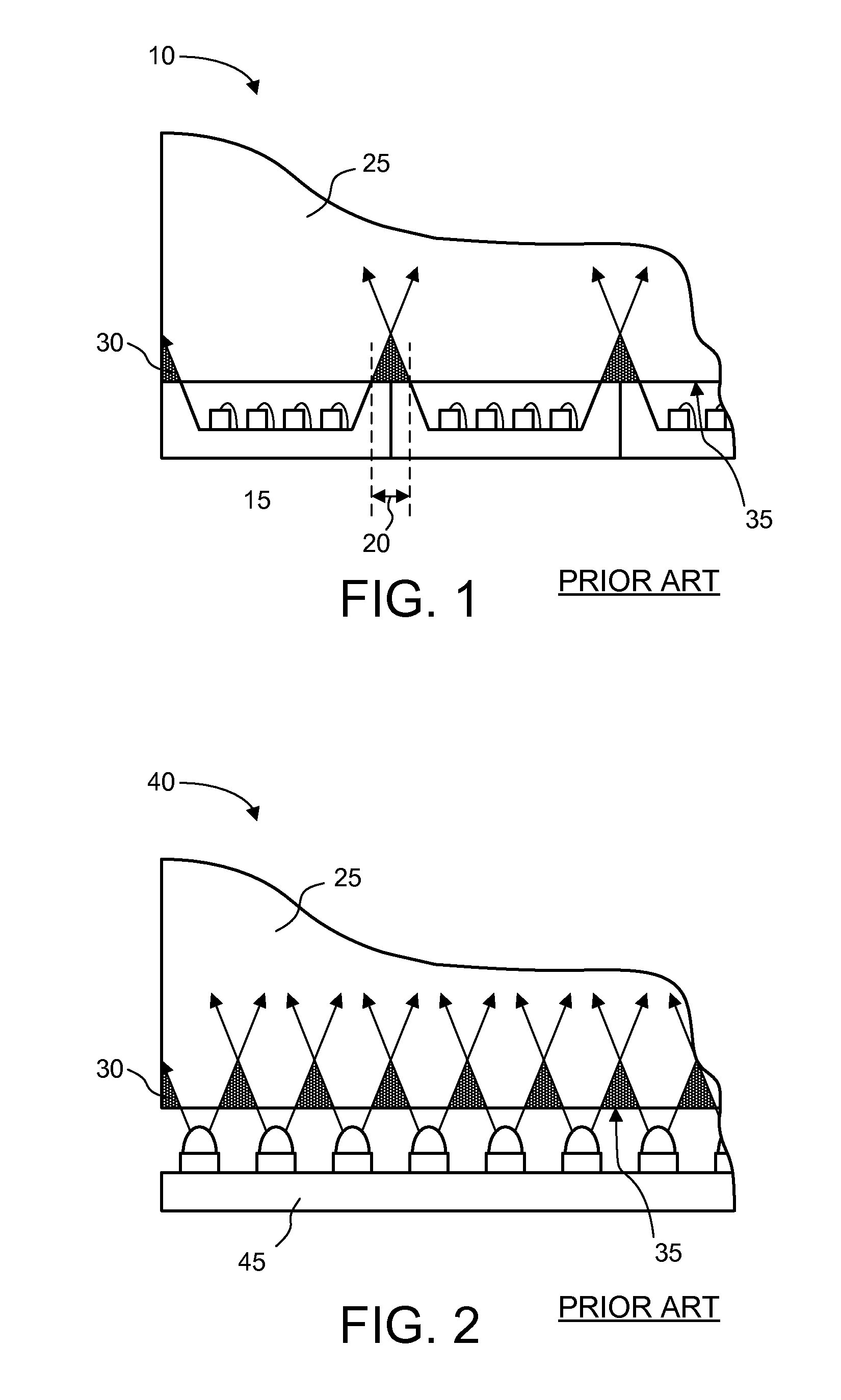
[0030]FIG. 1 depicts a conventional light system 10 which uses LED devices 15 having LEDs encapsulated in a common encapsulant. Each LED device 15 has reflector walls, or sidewalls (i.e., the structural walls separating the LED dice, or chips, on adjacent LED devices), at both ends of the LED device. The separation distance between LEDs of adjacent LED devices is called pitch 20. The pitch 20 between the LED devices 15 at least partially determines the light pattern within the light guide plate 25. One example of a light guide plate 25 is a diffusion panel such as may be used in a liquid crystal display (LCD) panel.

[0031]The use of LED devices 15 with sidewalls to illuminate a light guide plate 25 results in dark spots 30 on the light guide plate 25. The dark spots 30 are due to the pitch 20 of the sidewalls of the LED devices 15 because the sidewalls block and prevent the light from mixing and passing through the transmission interface 35 (i.e., the edge through which the light ent...


PUM


Abstract

A lighting apparatus is described. One embodiment of the lighting apparatus includes a substrate and a lighting element. The lighting element is coupled to the substrate to emit light through a light exit plane. The light exit plane is substantially perpendicular to the substrate. By providing a lighting device with a substrate oriented perpendicular to the light exit plane of the lighting device, the lighting device can enable better mixing of the light from different LEDs. The lighting apparatus facilitates light mixing, generally, to minimize or eliminate dark spots on the diffusion panel. The lighting device also facilitates color mixing to produce relatively consistent white light on the diffusion panel.

Description

BACKGROUND OF THE INVENTION[0001]Most liquid crystal display (LCD) panels use backlighting to provide a bright image to the viewer. Backlighting is typically provided by diffusing white light from a fluorescent light source or several light emitting diode (LED) sources. To provide evenly distributed backlighting, LCD panels have a diffusion panel that receives the light along one edge of the panel and diffuses the light throughout the face of the diffusion panel. The white light may be directly generated by the fluorescent light source or the LEDs. However, colored LEDs emitting such colors as red, green, and blue (RGB) are also used in some applications. Where colored LEDs are used, the different colors are mixed to create the white light.[0002]In applications that use LEDs, several LEDs typically are mounted on a single substrate. The LEDs and substrate are referred to as an LED device. One type of LED device is referred to as an LED array. Some LED arrays have individual lenses f...

Claims


Application Information

Patent Timeline
Patent Type & Authority Patents(United States)
IPC IPC(8): F21V7/04F21V29/505H01L33/60
CPCG02B6/0031G02B6/0073G02B19/0066G02B19/0028F21V7/0008F21V29/004F21V31/04F21Y2101/02G02B6/0068H01L2224/48091H01L33/60H01L2924/00014F21K9/64F21Y2115/10F21V29/503
Inventor CHEW, TONG FATTPANG, SIEW ITYOGANANDAN, SUNDAR NATARAJANNG, KEE YEAN
Owner AVAGO TECH INT SALES PTE LTD
Why Eureka
Try Eureka