Candle wick straightening method and apparatus

a straightening method and apparatus technology, applied in the field of candles, can solve the problems of inability to keep the wick straight, time-consuming procedure, and no method or reusable device in the related art in this field, and achieve the effects of simple and easy use, low cost, and faster work

Inactive Publication Date: 2010-06-15
HORVATH DAIVID G +1
View PDF20 Cites 12 Cited by
  • Summary
  • Abstract
  • Description
  • Claims
  • Application Information

AI Technical Summary

Benefits of technology

[0023]A wick straightening apparatus is provided which includes a narrow tube or sleeve and crosspiece preferably adapted to slide up and down along the tube. The sleeve is sized to snugly fit around a wick and wick clip or holder, and the upper end of the tube is closed or airtight. The crosspiece, which slides up and down the tube, can be made in a variety of lengths or widths, but such width must be greater than the width of the jar opening, so it can rest on the jar lip while the apparatus is in use. The top portion of the crosspiece may be rounded to more ergonomically fit the design of one's hand, although the bottom portion should remain flat at least on the ends so that it rests evenly upon the jar lip. Such device is simple and easy to use and will enable a candle maker to work more quickly as compared to prior art wick straightening devices and methods. In use, first a candle maker will insert the upper end of a wick having a wick holder or clip support attached on its lower end into the wick-straightening device or apparatus. The wick apparatus is then inserted into a jar-type container filled with molten wax. After the wax cools, the wick apparatus is simply pulled out of the jar, leaving the wick and wick holder in the jar, and additional wax is then poured into the jar to fill in the concave depression that formed when the original wax cooled as well as into the area previously occupied by the wick apparatus tube or sleeve. Once such additional wax has cooled, the candle is complete with a straight wick, and the wick apparatus can then be immediately reused for the next batch of candles to be made. There is no preparation or cleaning of the wick straightener apparatus required after each use, since wax is prevented from entering the tube or sleeve, which has a closed or airtight upper end, by air trapped in the tube prior to insertion into the jar. Since the apparatus can be made out of fairly low cost materials such as plastic, candle makers can keep large quantities of them on hand and replacement costs are minimal. The wick straightener of the invention also allows the candle maker to be confident that the bottom wick tab is precisely centered by the fact that the top is of the wick straightener tube or sleeve can be visually centered, even in dark deep containers where the bottom of the jar may not be visible.

Problems solved by technology

However, these candles have posed a problem for candle makers during the pouring process because they are not able to keep the wick straight in the same manner as is used for candles not contained in a jar or container.
However, none of the related art in this field has supplied a method or reusable device that enables a candle maker to easily and efficiently insert a wick and guarantees that it maintains its vertical position as well as the present inventor's device.
While Berman is somewhat useful in maintaining the wick straight and centered, the candles in Berman are poured into jars and containers having holes through the bottom, and in addition the wick must be tied and untied from the bar on top of the jar, which can be a time costly procedure.
Simply cutting the wick would also lead to wasted materials and therefore an increase in production costs.
Schmitt et al. does not teach a device for making candles in a jar or container, and in addition, manually stringing the wick through the core is a time costly procedure.
Such method is slow and cumbersome because the wick must be manually threaded down through the candle and into the wick base, which task is inefficient and time consuming.
Such method is not applicable to candles formed in jars or containers.

Method used


Image

  • Candle wick straightening method and apparatus
  • Candle wick straightening method and apparatus
  • Candle wick straightening method and apparatus

Examples


Embodiment Construction

[0033]The following detailed description is of the best mode or modes of the invention presently contemplated. Such description is not intended to be understood in a limiting sense, but to be an example of the invention presented solely for illustration thereof, and by reference to which in connection with the following description and the accompanying drawings one skilled in the art may be advised of the advantages and construction of the invention.

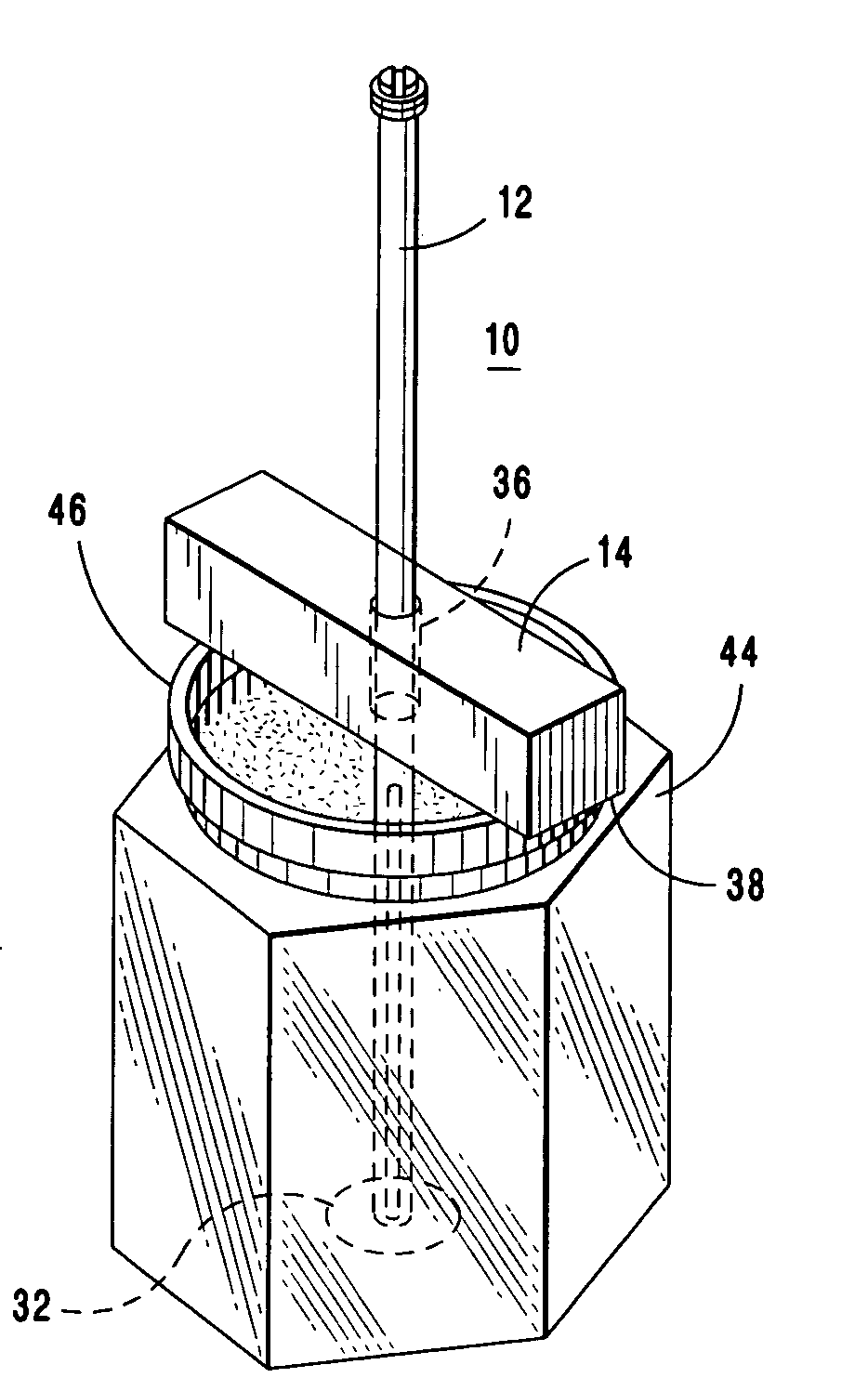
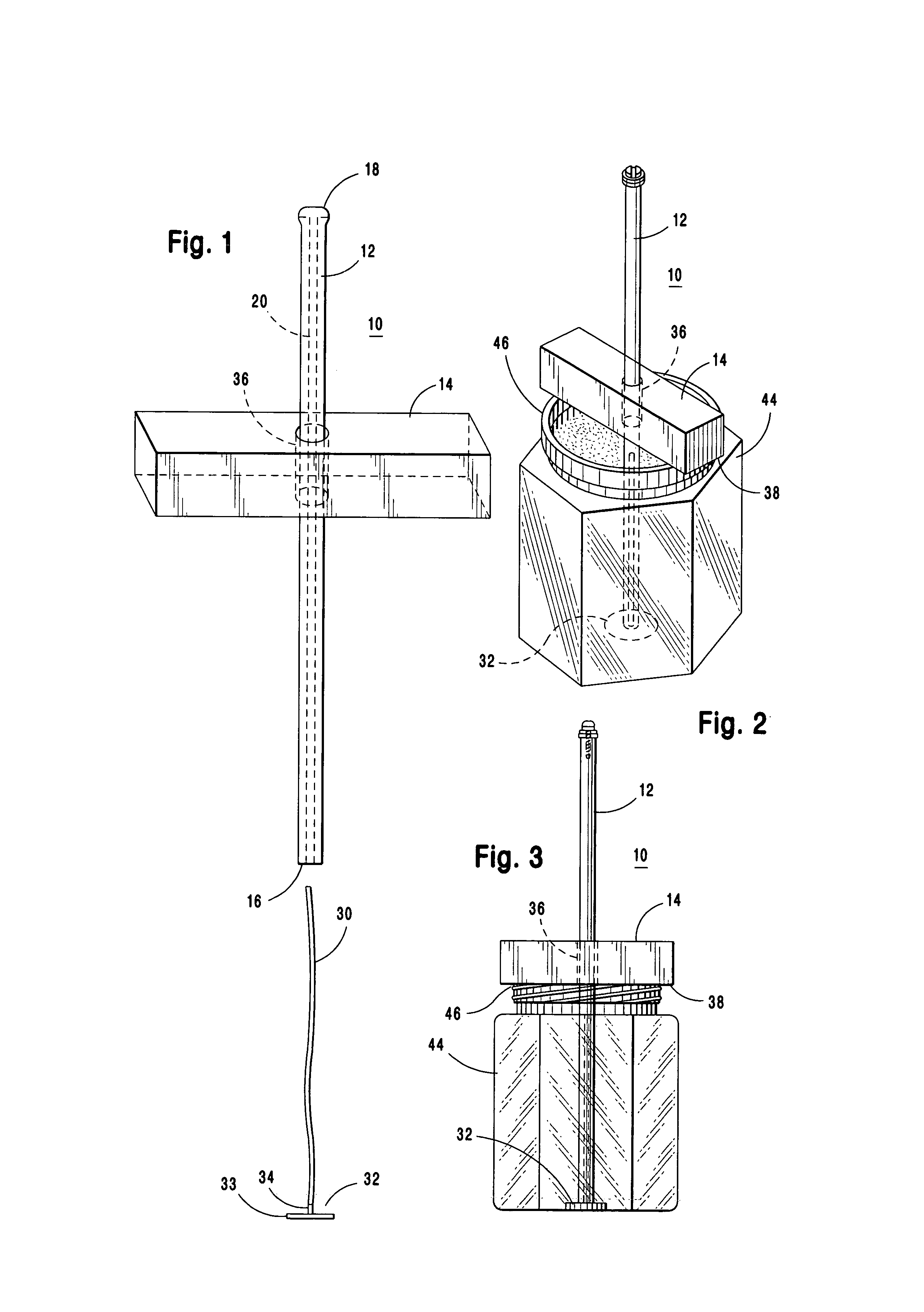
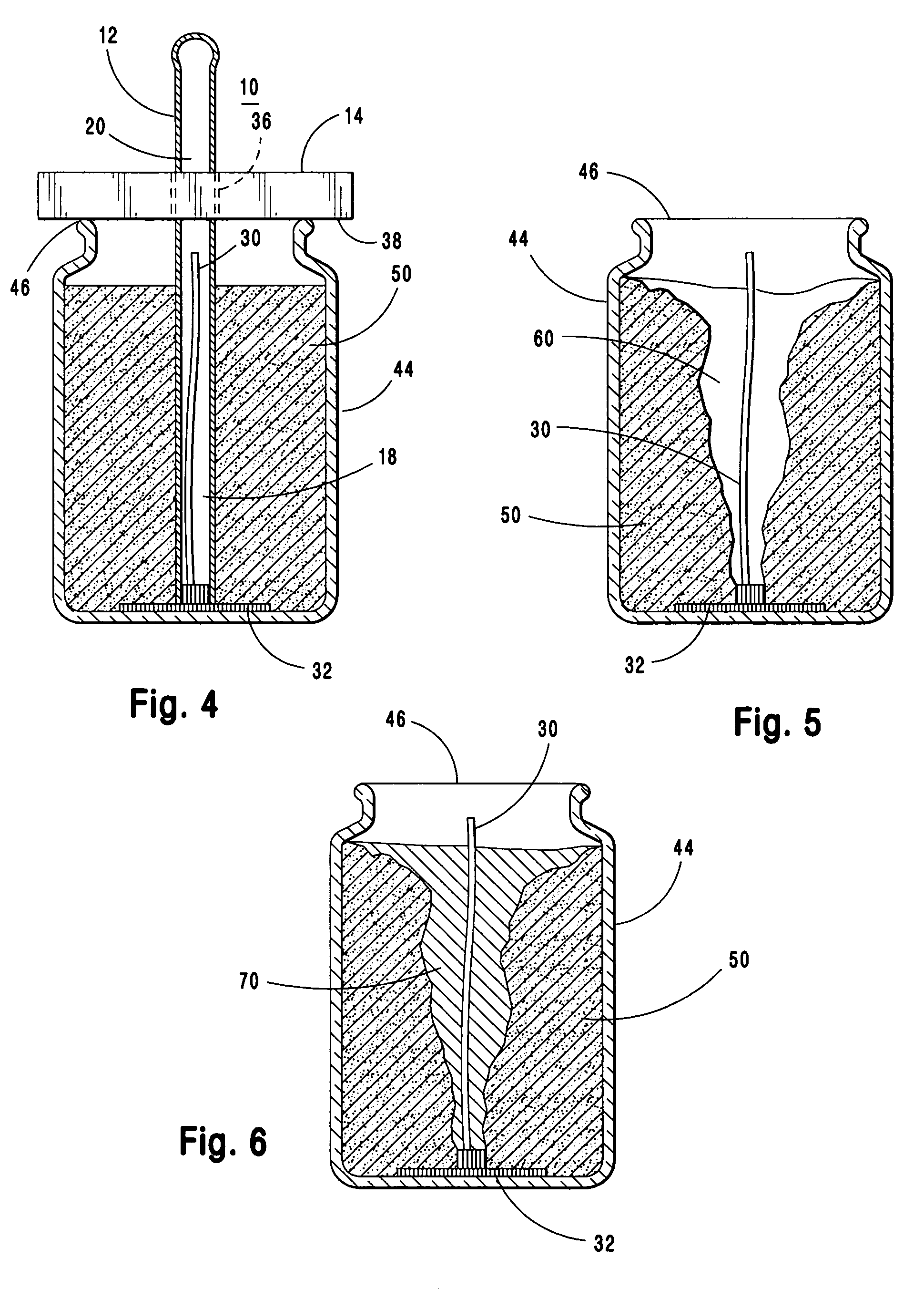
[0034]Typically, in manufacturing candles in a jar-type container, such as a glass jar having an inner wall and a floor or closed bottom, first the wick is attached on one end to a wick holder or clip, which is then situated centrally on the interior bottom of the container. Next a so-called fuel, which is formed of a wax such as paraffin, is heated and is poured into the jar or container so that the wick is surrounded by the fuel. Paraffin wax is a heavy hydrocarbon that is a solid at room temperature, but easily melted by heat, and is ...


PUM

PropertyMeasurementUnit
forceaaaaaaaaaa
shapesaaaaaaaaaa
sizesaaaaaaaaaa

Abstract

A method and apparatus for inserting wicks into candles formed in jars or containers characterized by a device comprised of a hollow tube, sealed on one end, in which a wick and wick base can snugly fit, and a crosspiece having width greater than width of the mouth of a jar so that after candle wax is poured, the wick straightening device is inserted into the jar and is removed after the wax has cooled so that the wick will remain straight even after the candle wax has cooled.

Description

BACKGROUND OF THE INVENTION[0001]1. Field of the Invention[0002]The present invention relates to making candles. More particularly, this invention relates to a method of easily and efficiently inserting a wick into a candle being formed in a jar-type container, and more particularly still to an apparatus and method for maintaining a candle wick straight and centered while the liquid fuel or wax is being poured and is cured.[0003]2. Preliminary Discussion[0004]The word candle derives from the Latin ‘Candere,’ meaning to flicker or glitter. Prior to about 1825, candles were comprised of a single stranded wick, rather than a braided wick, and therefore burned very unevenly. The introduction of paraffin wax as a cheaper replacement for beeswax as a liquid fuel in the 19th century, as well as the development of means for mass producing of candles, resulted not only in candles becoming common in most households but also made them available in a variety of shapes and sizes.[0005]While such...

Claims


Application Information

Patent Timeline
Patent Type & Authority Patents(United States)
IPC IPC(8): F23D3/34
CPCF23D3/34
Inventor HORVATH, DAIVID G.GALLAGHER, BRIAN
Owner HORVATH DAIVID G
Why Eureka
Try Eureka