X-ray window with grid structure

a grid structure and x-ray window technology, applied in the field of radiation detection systems, can solve the problems of many known support structures having drawbacks, overlaid thin film can stretch, weaken and burst, and many support structures can interfere with the passage of radiation, so as to minimize interference with the passage, reduce the effect of material cost and high strength

Inactive Publication Date: 2010-06-15
MOXTEK INC
View PDF125 Cites 41 Cited by
  • Summary
  • Abstract
  • Description
  • Claims
  • Application Information

AI Technical Summary

Benefits of technology

[0005]Accordingly, it has been recognized that it would be advantageous to develop a radiation detection system having a high strength, yet thin radiation detection window that is economical to manufacture, and further has the desirable characteristics of being minimally absorptive and minimizing interference with the passage of radiation therethrough. It is also desirable to provide a radiation window having a support structure that will maintain intact thin films that overlay the support structure.

Problems solved by technology

While useful for providing support to an often thin and fragile sheet of material, many support structures can interfere with the passage of radiation through the sheet of material due to the structure's geometry, thickness and / or composition.
The interference can be the result of the composition of the material itself and / or the geometry of the support structure.
In addition, many known support structures have drawbacks.
For example, screens and meshes can be rough and coarse, and thus the overlaid thin film can stretch, weaken and burst at locations where it contacts the screen or mesh.
A drawback associated with unidirectional ribs is that the ribs can twist when pressure is applied.
This twisting can also cause the overlaid film to stretch weaken and burst.
Additionally, there can be substantial difficulty in manufacturing many known support structures, thus resulting in increased expense of the support structures and associated windows.

Method used


Image

  • X-ray window with grid structure
  • X-ray window with grid structure
  • X-ray window with grid structure

Examples


Embodiment Construction

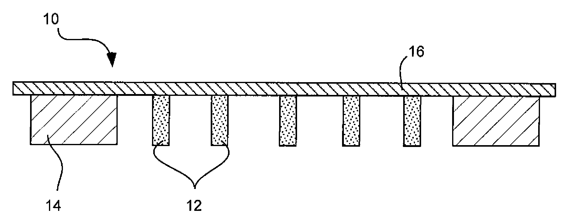
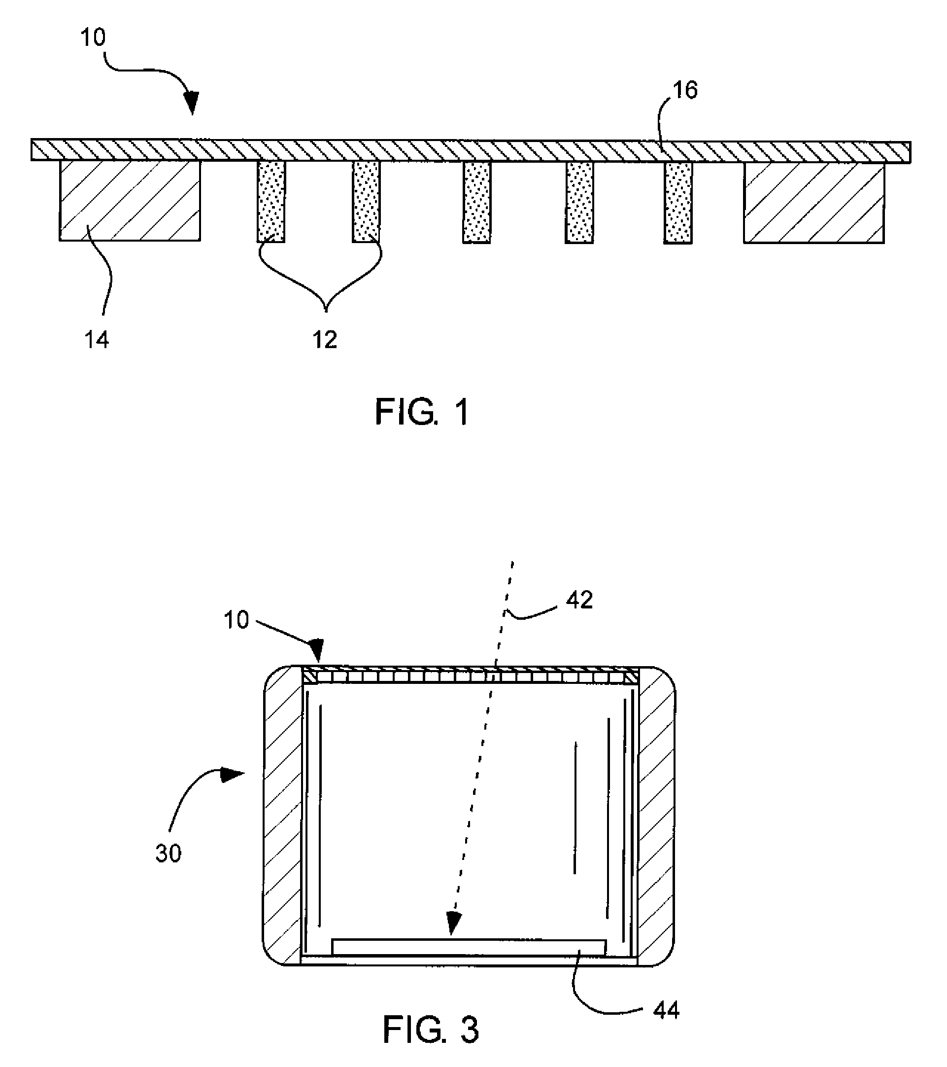
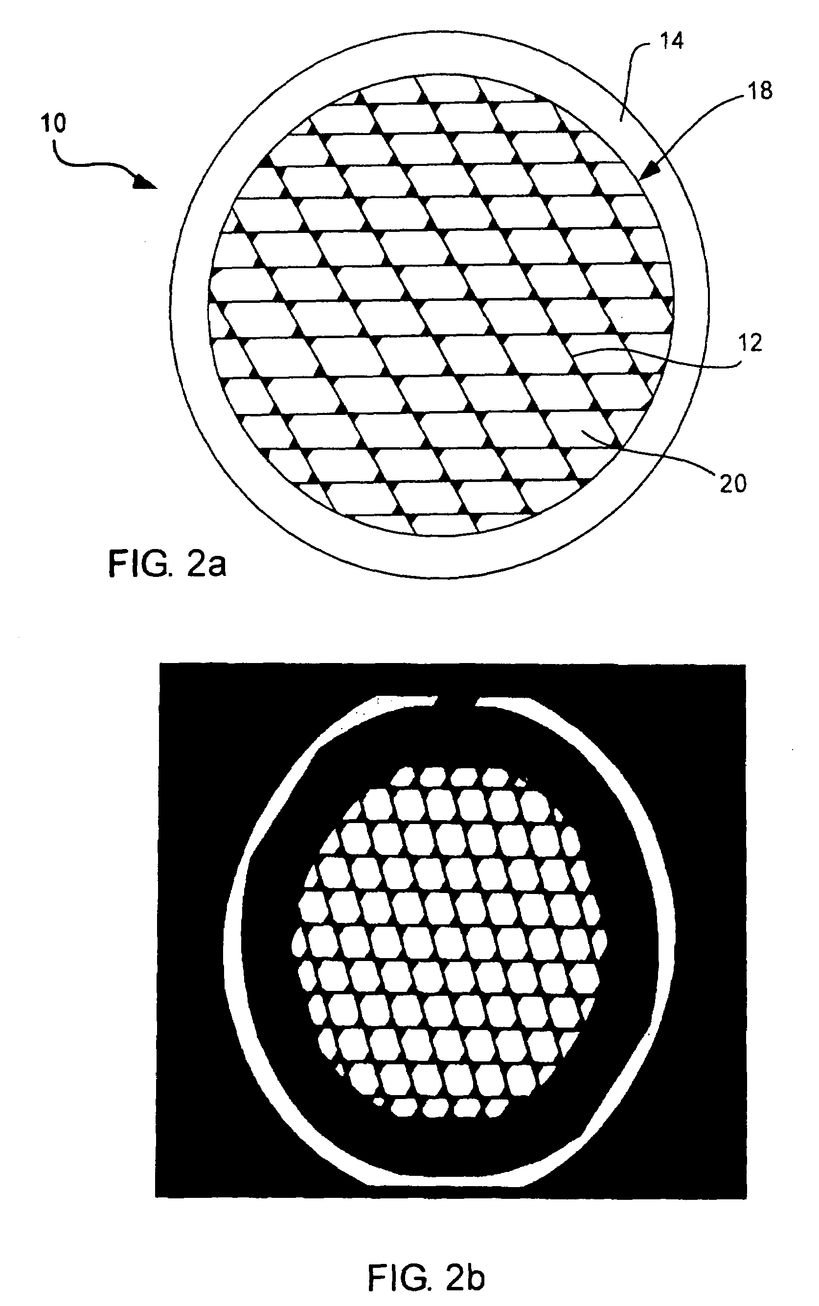
[0013]Reference will now be made to the exemplary embodiments illustrated in the drawings, and specific language will be used herein to describe the same. It will nevertheless be understood that no limitation of the scope of the invention is thereby intended. Alterations and further modifications of the inventive features illustrated herein, and additional applications of the principles of the inventions as illustrated herein, which would occur to one skilled in the relevant art and having possession of this disclosure, are to be considered within the scope of the invention.

[0014]The present invention provides embodiments pertinent to a high strength window for a radiation detection system, an associated radiation detection system, and an associated method of manufacturing a high strength grid for a window in a radiation detection system. In accordance with these embodiments, various details are provided herein which are applicable to all three of the window, system and method.

[0015...


PUM


Abstract

A high strength window for a radiation detection system includes a plurality of intersecting ribs defining a grid having openings therein with tops of the ribs terminate substantially in a common plane. The intersecting ribs are oriented non-perpendicularly with respect to each other and define non-rectangular openings. The window also includes a support frame around a perimeter of the plurality of intersecting ribs, and a film disposed over and spanning the plurality of intersecting ribs and openings. The film is configured to pass radiation therethrough. An associated radiation detection system includes a sensor disposed behind the window. The sensor is configured to detect radiation passing through the high strength window.

Description

FIELD OF THE INVENTION[0001]The present invention relates generally to radiation detection systems and associated high strength radiation detection windows.BACKGROUND[0002]Radiation detection systems are used in connection with detecting and sensing emitted radiation. Such systems can be used in connection with electron microscopy, X-ray telescopy, and X-ray spectroscopy. Radiation detection systems typically include in their structure a radiation detection window, which can pass radiation emitted from the radiation source to a radiation detector or sensor, and can also filter or block undesired radiation.[0003]Standard radiation detection windows typically comprise a sheet of material, which is placed over an opening or entrance to the detector. As a general rule, the thickness of the sheet of material corresponds directly to the ability of the material to pass radiation. Accordingly, it is desirable to provide a sheet of material that is as thin as possible, yet capable of withsta...

Claims


Application Information

Patent Timeline
Patent Type & Authority Patents(United States)
IPC IPC(8): G02B5/00G21K1/00H01J1/52H01J29/46H01J3/00H01J5/18
CPCH01J47/004H01J5/18
Inventor XU, DEGAOANDERSON, ERIC C.DECKER, KEITH W.PERKINS, RAYMOND T.
Owner MOXTEK INC
Why Eureka
Try Eureka