Control apparatus and method for use with digitally controlled light sources

a technology of control apparatus and control method, applied in the field of light, to achieve the effect of reducing the flicker of perceivable ligh

Active Publication Date: 2010-06-15
SIGNIFY HLDG BV
View PDF23 Cites 32 Cited by
  • Summary
  • Abstract
  • Description
  • Claims
  • Application Information

AI Technical Summary

Benefits of technology

[0034]A particular advantage of the present invention is that the difference in pulse width modulation duty factor between m pulse cycles and the (2M−m) pulse cycles is 1 / N. As noted in for example the IESNA Lighting Handbook, Ninth Edition, pp. 3-21-3-22, the perception of visual flicker of a light source or a surface illuminated thereby is dependent on both temporal frequency and contrast. Whereas a pulse-width modulated light source with 100 percent modulation has a contrast value of 0.01, an extended pulse-width modulated light source has (100 / 2N) percent modulation and a contrast value of (2N / 100). Thus, while a light source with a PWM frequency of for example 50 Hertz will exhibit visual flicker in accordance with FIG. 1 (adapted from IESNA Lighting Handbook, Ninth Edition, FIG. 3-34), the same light source with an extended PWM frequency of 800 Hertz and N=4 will exhibit no visual flicker, as it has a contrast value of 0.16.
[0035]In an alternate embodiment, controlling the effective pulse width can include, for example, first providing n for (2M−m) pulses and subsequently n+1 for m pulses or optionally modulating the pulse widths per pulse cycle in decrements of one. In these scenarios however, n=0 may require an exception from the normal procedure. Furthermore, controlling the effective pulse width may include varying the pulse widths per pulse cycle by more than one or controlling the effective pulse width may include randomly varying the pulse widths in the stream of pulse cycles.
[0036]The method and apparatus according to the present invention permits choosing the pulse cycle frequency as an independent parameter while modulating the pulse widths. The pulse cycle frequency can be chosen such that attached light-emitting elements, for example LEDs, can be effectively operated under negligible thermal stress conditions and / or the modulation frequency can be chosen sufficiently high to help reduce perceivable light flicker. In one embodiment of the present invention the pulse cycle frequency is selected to be greater than or equal to about 20 kHz. In another embodiment, the pulse cycle frequency is selected to be about 30 kHz.
[0037]FIG. 2 illustrates a block diagram of one embodiment of the present invention for use with a single or multi-channel lighting apparatus. An interface controller 370 provides functionality to forward a signal comprising an (N+M)-bit binary signal comprising a number n, represented by the most significant N bits, and a number m, represented by the least significant M bits of this (N+M)-bit binary signal. The interface controller 370 controls the extended pulse width modulator 372, wherein the extended pulse width modulator generates a signal comprising an N-bit pulse width modulation signal and forwards it to an N-bit single or multi-channel pulse width modulation controller 374. A clock 373 provides the extended pulse width modulator 372 with a synchronisation signal having a predetermined frequency, wherein the clock 373 can be a separate or an integral part of the extended pulse width modulator 372. In this manner the pulse width modulator can process or generate dependent or multiple independent signals for a single or multi-channel pulse width modulation controller 374 which can control multiple channels of light-emitting elements such as LEDs with an effective resolution of 2N+m.
[0038]The single or multi-channel pulse width modulation controller 374 can be attached to a single or multi-colour light-emitting element luminaire 376, wherein a multi-colour luminaire can comprise light-emitting elements that emit one or more light ranges selected from red, green, blue, amber and white, for example. Light-emitting elements associated with a luminaire can be categorized according to their intended colour impression into multiple colour channels, wherein each colour channel can have its own single-channel pulse width modulation controller or can be operatively connected to one predetermined channel of a multi-channel pulse width modulation controller. The single- or multi-channel pulse width modulation controller can be connected to a single or multi-colour channel luminaire that can have a combination of red, green, blue, amber or any other coloured or otherwise categorized light-emitting elements, for example.
[0039]A luminaire that can be controlled using the method and apparatus according to the present invention is illustrated as a block diagram in FIG. 3. The luminaire 100 comprises a number of components including a power supply 110, a power converter 120, a controller 140, and a light source 130. Each component comprises an input for receiving an input signal, and an output for providing an output signal, however only selected inputs and outputs of these components are illustrated in FIG. 3. Under operating conditions the power supply 110 requires a certain form of electrical power at its input and provides a form P of electrical power at its output. The output of the power supply 110 is connected to the input of the power converter 120, wherein the power converter 120 transforms the electrical power P provided at its input into an electrical drive current Ii which the power converter 120 provides at its output. This electrical drive current Ii is provided to the light source 130 for operation thereof. The controller 140 is operatively coupled to the power converter 120, wherein the controller 140 provides a drive current control signal Is to the power converter 120. The controller 140 comprises or is adapted for connection to the control apparatus according to the present invention, thereby enabling the controller 140 to control the power converter 120 with a resolution level of 2N+M states. Furthermore, the controller 140 can be responsive to signal Id provided at an (optional) interface input or other input means for example. For example, Id can be a user desired dimming sequence.

Problems solved by technology

However, certain applications only require controlling the average light output over time.

Method used


Image

  • Control apparatus and method for use with digitally controlled light sources
  • Control apparatus and method for use with digitally controlled light sources
  • Control apparatus and method for use with digitally controlled light sources

Examples


example 1

Solid-State Luminaire with Extended Pulse Code Modulation Control

[0063]According to one embodiment of the present invention a solid-state lighting luminaire can be configured as illustrated in FIG. 4, wherein the extended pulse width modulation as defined above is implemented in firmware on the controller 140, for example a commercial microcontroller, by using the extended pulse code modulation method as illustrated FIGS. 11 to 13. One or more calibrations are implemented on the controller resulting from collected data reflecting one or more of chromaticity, luminous flux, temperature of the LEDs and drive current, thereby enabling feedback control of the solid-state luminaire.

example 2

Solid-State Luminaire with Extended Pulse Width Modulation Control

[0064]According to one embodiment of the present invention a solid-state lighting luminaire can be configured as illustrated in FIG. 4, wherein the extended pulse width modulation as defined above is implemented in firmware on the controller 140, for example a commercial microcontroller, by using the extended pulse width modulation method as illustrated FIGS. 8 to 10. The controller can comprise one or a plurality of integrated 10-bit analog-to-digital converter modules, wherein other functions may also be implemented, such as for example sensor monitoring and feedback control.

example 3

Solid-State Luminaire with Extended Pulse Code Modulation Control

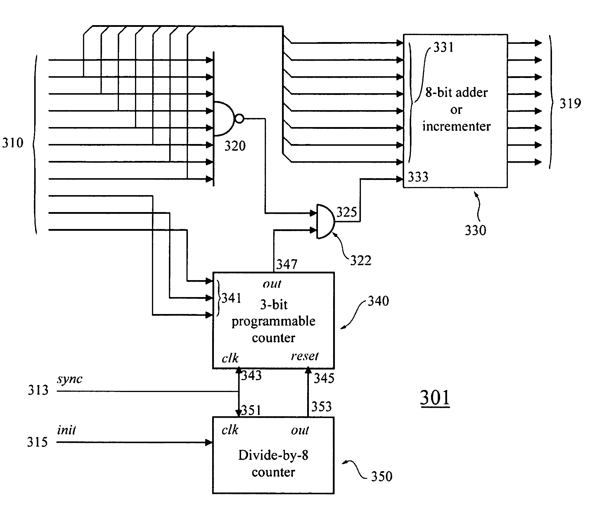
[0065]Referring to FIG. 4, the extended pulse width modulation method disclosed herein may be implemented in the controller 140 using the extended pulse width modulation as disclosed in FIGS. 11 to 13 implemented in hardware using for example a field-programmable gate array (FPGA) with preferably a microcontroller core. Other functions may be implemented within the luminaire including for example sensor monitoring and feedback control.


PUM


Abstract

The present invention provides an extension to a standard N-bit digital pulse width control method which can discriminate 2N discrete pulse widths per pulse cycle. The present invention provides a method and apparatus that can modulate the pulse widths over a period of 2M pulse cycles in which each pulse cycle can have its own pulse width or respective duty cycle. The resulting time averaged or effective pulse width therefore can be controlled with a resolution of 2N+M states rather than a resolution of 2N states as is common with standard methods.

Description

FIELD OF THE INVENTION[0001]The present invention pertains to the field of lighting and in particular to a method and apparatus for controlling the amount of light emitted by one or more digitally controlled light sources.BACKGROUND[0002]Advances in the development and improvements of the luminous flux of light-emitting diodes (LEDs) such as solid state and organic light-emitting diodes have made these devices suitable for use in general illumination applications, including architectural, entertainment, and roadway lighting, for example. As such, light-emitting diodes are becoming increasingly competitive with light sources such as incandescent, fluorescent, and high-intensity discharge lamps.[0003]Light-emitting diodes offer a number of advantages and are generally chosen for their ruggedness, long lifetime, high efficiency, low voltage requirements, and the possibility to control the colour and intensity of the emitted light independently. They provide improvement over delicate ga...

Claims


Application Information

Patent Timeline
Patent Type & Authority Patents(United States)
IPC IPC(8): G09G5/10H04W48/16H04W52/02H04W64/00H05B44/00
CPCH03K7/08H04W52/0229H05B33/0818H05B33/0851H05B33/0857H05B33/0869H05B33/0872G09G3/2014G09G2320/0247G09G2330/028H04W48/16Y02B20/346H04W64/006H05B45/14Y02D30/70H05B45/20H05B45/37Y02B20/30H05B45/22
Inventor ASHDOWN, IANROBINSON, SHANE P.
Owner SIGNIFY HLDG BV
Why Eureka
Try Eureka