Liquid crystal display device

a liquid crystal display and display device technology, applied in the direction of instruments, optical light guides, optics, etc., can solve the problems of difficult to adjust the color temperature without lowering the light use efficiency, the driving method is complicated, and the difficulty of raising the light use efficiency and reducing the cost of the device, so as to achieve high color reproducibility, high color temperature, and high quality images

Active Publication Date: 2010-06-15
FUJIFILM CORP
View PDF14 Cites 31 Cited by
  • Summary
  • Abstract
  • Description
  • Claims
  • Application Information

AI Technical Summary

Benefits of technology

[0019]The method using the three different LEDs having the center wavelengths in ranges for red, green, and blue, respectively, is advantageous in that light representing a desired color can be emitted through the light emission face by adjusting the wavelengths and the luminescence intensities of the light emitted by the respective LEDs. However, the method presents some problems: control is made difficult by the fact that the properties such as temperature characteristics vary among the three different LEDs; the driving method used is complicated. Another problem is the difficulty encountered in raising the light use efficiency and reducing the costs of the device.
[0063]Thus, according to the present invention, light with a high brightness or a high illuminance can be efficiently emitted through the light exit plane while achieving a thin design of the device.

Problems solved by technology

However, the method presents some problems: control is made difficult by the fact that the properties such as temperature characteristics vary among the three different LEDs; the driving method used is complicated.
Another problem is the difficulty encountered in raising the light use efficiency and reducing the costs of the device.
However, such light source has its share of problems: light produced by a blue LED having a phosphor applied thereto has a low color temperature and it is difficult to adjust the color temperature without lowering the light use efficiency.
Accordingly, light emitted through the light exit plane of a planar lighting device has a low color temperature, and the adjustment is difficult.

Method used


Image

  • Liquid crystal display device
  • Liquid crystal display device
  • Liquid crystal display device

Examples


Embodiment Construction

[0097]Now, preferred embodiments of the liquid crystal display device according to the present invention will be described in detail by referring to the accompanying drawings.

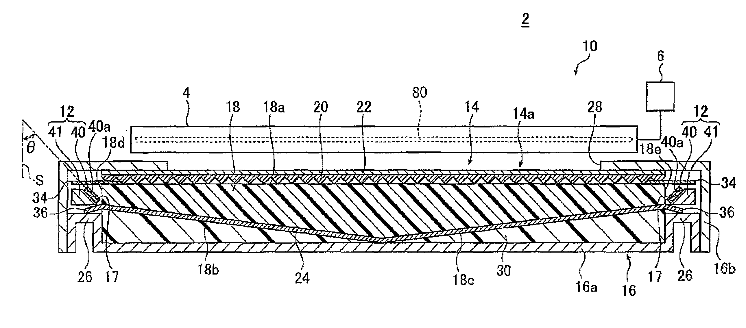
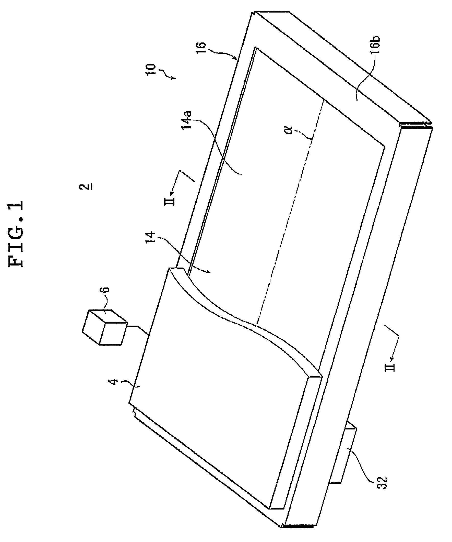
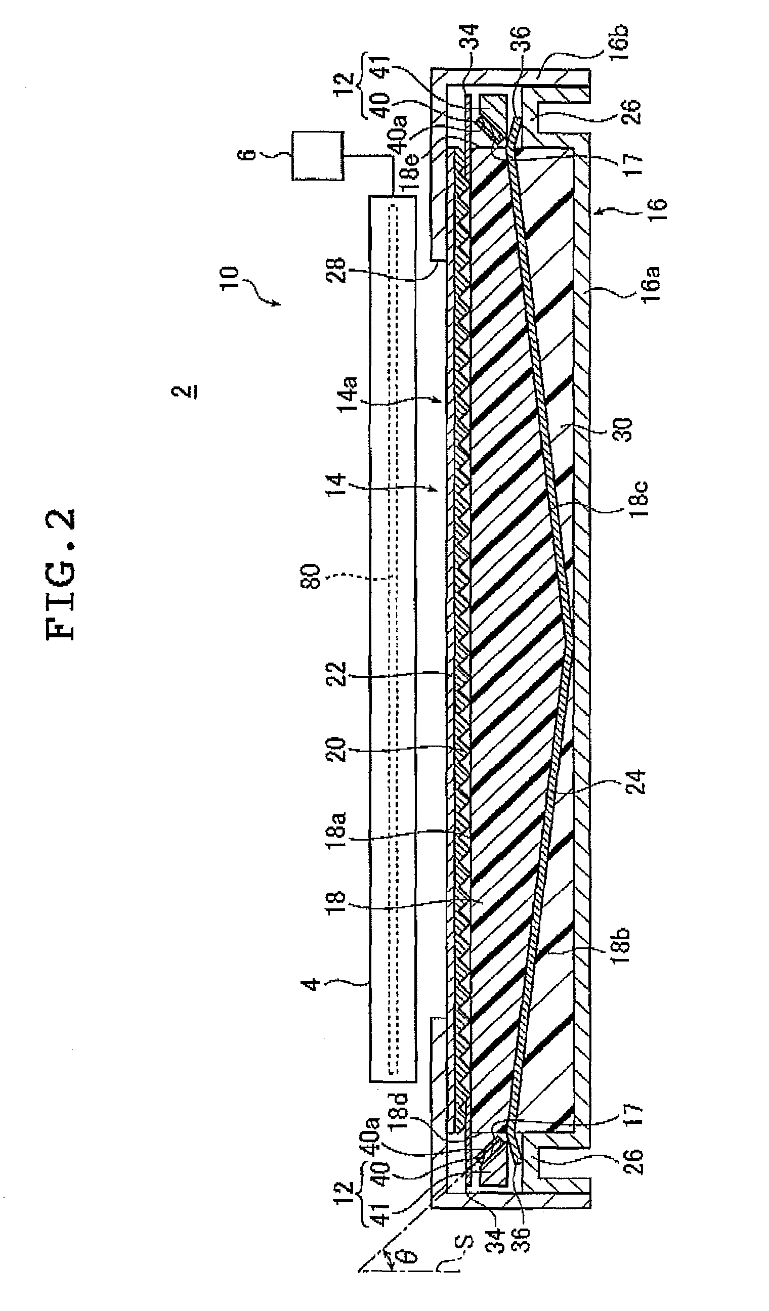
[0098]FIG. 1 is a perspective view illustrating an embodiment of the inventive liquid crystal display device. FIG. 2 is a sectional view of the liquid crystal display device illustrated in FIG. 1 taken along the line II-II, FIG. 5 is an enlarged sectional view illustrating part of the liquid crystal display device of FIG. 2 enlarged.

[0099]As illustrated in FIGS. 1 and 2, a liquid crystal display device 2 comprises a planar lighting device 10, a liquid crystal display panel 4 disposed on the side of the planar lighting device 10 closer to a light exit plane, and a drive unit 6 for driving the liquid crystal display panel 4. FIG. 1 omits part of the liquid crystal display panel 4 to better illustrate the structure of the planar lighting device.

[0100]The liquid crystal display panel 4 comprises a liquid crystal ce...


PUM

PropertyMeasurementUnit
wavelengthaaaaaaaaaa
full-width at half-maximumaaaaaaaaaa
peak wavelengthaaaaaaaaaa

Abstract

The liquid crystal display device with a simple configuration is capable of emitting light with a desired color temperature, achieving high light use efficiency, and displaying high quality images. The liquid crystal display device includes a planar lighting device and a liquid crystal display panel. The planar lighting device includes a light source having LED chips for emitting blue light, a transparent light guide plate having a light entrance plane admitting light emitted by the light source and a light exit plane emitting planar light, and a fluorescent member disposed between the light emission plane and the light entrance plane and having one or more fluorescent substance coated areas for emitting white light by converting blue light from the light source into white light and one or more blue light passing areas passing blue light as blue light. The liquid crystal display panel essentially includes red, green and blue filters.

Description

[0001]The entire contents of documents cited in this specification are incorporated herein by reference.BACKGROUND OF THE INVENTION[0002]The present invention relates to a liquid crystal display device comprising a planar lighting device and a liquid crystal display panel, the former comprising a light guide plate that emits illuminating light through a light exit plane by diffusing light emitted by a light source.[0003]There is known a liquid crystal display device comprising a liquid crystal display panel and a backlight unit or a planar lighting device for illuminating the liquid crystal display panel by radiating light from behind the liquid crystal display panel. The backlight unit is configured using a light guide plate for irradiating the liquid crystal display panel by diffusing light emitted by an illuminating light source and optical members such as a prism sheet and a diffusion sheet.[0004]Backlight units currently used in liquid crystal display devices such as large liqu...

Claims


Application Information

Patent Timeline
Patent Type & Authority Patents(United States)
IPC IPC(8): G02F1/1335
CPCG02B6/0023G02B6/0073
Inventor OKUMURA, TAKAMITSUIWASAKI, OSAMUENDO, TOSHIAKI
Owner FUJIFILM CORP
Why Eureka
Try Eureka