Method and apparatus for static timing analysis in the presence of a coupling event and process variation

a technology of coupling event and static timing, applied in the field of design automation, can solve the problems of signal slowdown, gate and wire delay and slew changes, and the conventional static timing analysis does not take into account the effect of coupling noise on timing, so as to reduce pessimism and increase the accuracy of performing statistical timing analysis

Inactive Publication Date: 2010-06-15
INT BUSINESS MASCH CORP
View PDF6 Cites 19 Cited by
  • Summary
  • Abstract
  • Description
  • Claims
  • Application Information

AI Technical Summary

Benefits of technology

[0016]These and other objectives are provided by the present invention. The invention increases the accuracy of performing a statistical timing analysis that includes coupling noise and reduces the pessimism as compared to conventional methods.

Problems solved by technology

Conventional static timing analysis, however, does not take into account the effect of coupling noise on timing.
Depending on how the signals rise or fall on these wires, capacitive coupling can cause changes in the delays and slews (transition times) of gates and wires.
Alternatively, if the two signals are switching in opposite directions, the effective capacitance is exacerbated, which can cause the signals to slow down.
Coupling in the form of interactions between adjacent wires causes disturbances that are not easily handled by a conventional static timing analysis.
This is because static timing relies on levelization of the timing graph, whereas due to coupling, gates and wires at different level numbers can impact each others' delays and slews.
Although some methods are known for analyzing coupling effects in STA, these prior-art methods do not take process variations into account.
Variations also impact coupling noise, and hence the change of timing characteristics due to coupling effects.
Treating coupling effects in a corner-based fashion (i.e., conducting the timing analysis with coupling considerations at one or more chosen deterministic settings of all process parameters) is pessimistic as well as inefficient.
Thus prior-art methods cannot accommodate both coupling events and process variations in an efficient or accurate manner.
A first drawback is that predicting the worst-case corner (or setting of process parameters that produces the worst-case timing result) is not immediately obvious, since when process parameters vary, some of the factors described above make the coupling event worse, and some factors make it better.
One possible result is an overlapping time window between the victim and aggressor, which will make the coupling event worse.
A second drawback is that using a worst-case analysis is needlessly pessimistic.
A simple worst-case analysis will not take these correlations into account and will predict a needlessly pessimistic result.
A third drawback is that for a thorough analysis, several combinations of process variations must be analyzed.
Such an exhaustive analysis, however, is inefficient.

Method used


Image

  • Method and apparatus for static timing analysis in the presence of a coupling event and process variation
  • Method and apparatus for static timing analysis in the presence of a coupling event and process variation
  • Method and apparatus for static timing analysis in the presence of a coupling event and process variation

Examples


Embodiment Construction

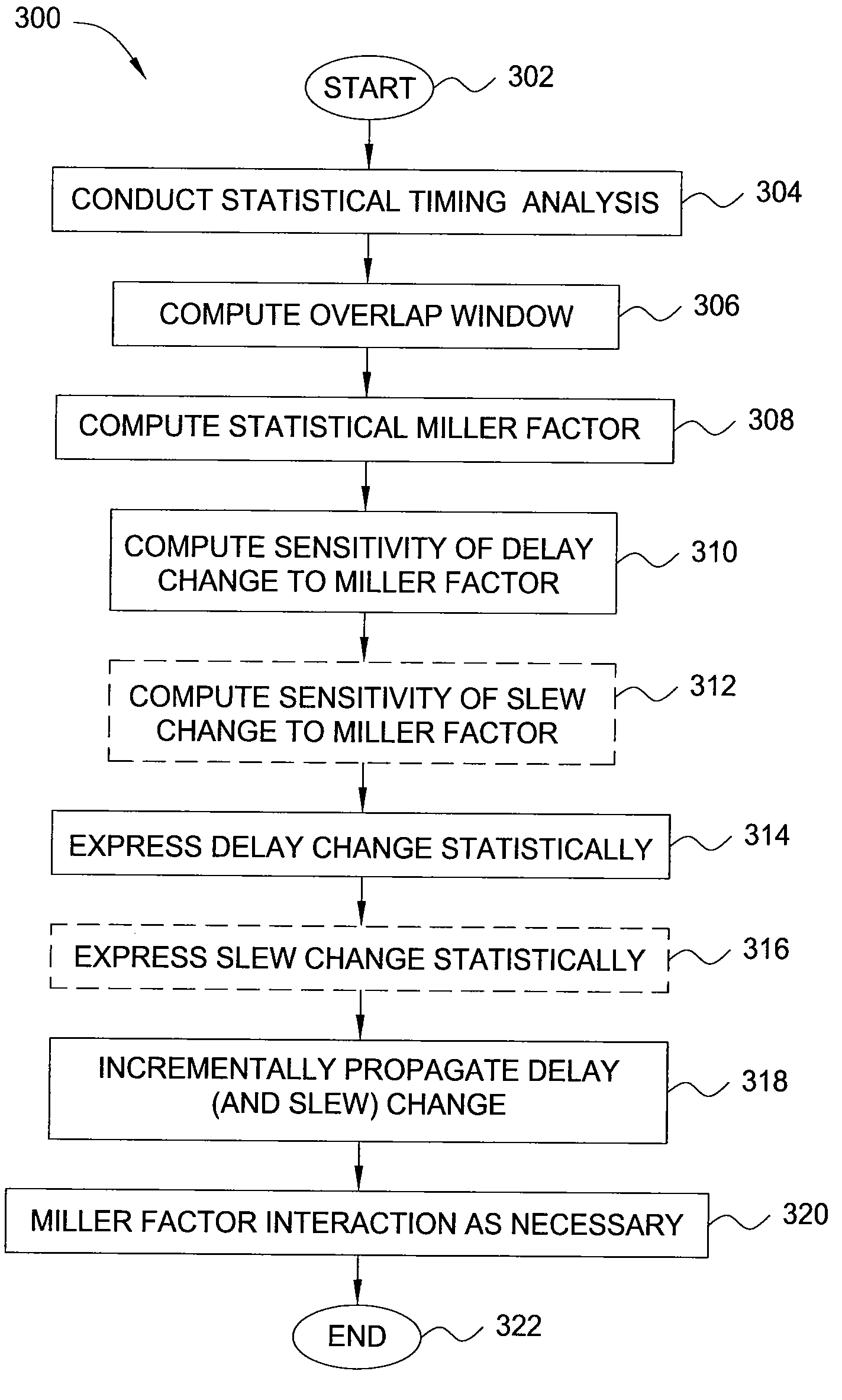
[0024]The present invention and the various features and advantageous details thereof are explained with reference to the non-limiting embodiments that are illustrated in the accompanying drawings and detailed in the following description. It should be noted that the features illustrated in the drawings are not necessarily drawn to scale. Descriptions of well-known components and processing techniques are omitted so as to not unnecessarily obscure the present invention in detail.

[0025]FIG. 3 is a flowchart illustrating one embodiment of a method 300 for static timing analysis of an integrated circuit design, according to the present invention. The method 300 may be implemented to analyze both combinational and sequential integrated circuit designs. As will be described in further detail below, the method 300 accurately and efficiently accounts for both process variations and coupling events during static timing analysis, while also taking into account the complex correlations induce...


PUM


Abstract

In one embodiment, the invention is a method and apparatus for static timing analysis in the presence of a coupling event and process variation. One embodiment of a method for computing a statistical change in delay and slew due to a coupling event between two adjacent nets in an integrated circuit design includes conducting a statistical timing analysis of the integrated circuit design, computing a statistical overlap window between the adjacent nets, where the statistical timing window represents a period of time during which signals on the adjacent nets can switch contemporaneously and computing the statistical change of delay due to the coupling event, in accordance with the statistical overlap window.

Description

FIELD OF THE INVENTION[0001]This invention generally relates to the field of Design Automation, and more particularly relates to statistical computation of the effects of coupling noise on static timing of integrated circuits.BACKGROUND OF THE INVENTION[0002]The primary goal of static timing analysis (STA) is to verify the timing correctness of integrated circuits. Conventional static timing analysis, however, does not take into account the effect of coupling noise on timing.[0003]Coupling capacitance exists when two neighboring wires in an integrated circuit are in close proximity to each other. Depending on how the signals rise or fall on these wires, capacitive coupling can cause changes in the delays and slews (transition times) of gates and wires. For example, if the signals on the two neighboring wires are switching in the same direction (i.e., both rising or both falling), then the coupling capacitances between the two wires have their two terminal voltages moving in the same...

Claims


Application Information

Patent Timeline
Patent Type & Authority Patents(United States)
IPC IPC(8): G06F17/50
CPCG06F17/5031G06F2217/84G06F30/3312G06F2119/12
Inventor ABBASPOUR, SOROUSHSCHAEFFER, GREGORY M.VISWESWARIAH, CHANDRAMOULI
Owner INT BUSINESS MASCH CORP
Why Eureka
Try Eureka