Translating active Gurney flap to alleviate aircraft wake vortex hazard

a technology of active gurney and flap, which is applied in the field of active gurney flap, can solve the problems of limiting airport capacity, creating potential hazards for following aircraft, and affecting the ability of airports to cope with the effects of wake vortex hazards, so as to reduce the large longitudinal spacing, minimize wake vortex hazards, and improve airport capacity

Inactive Publication Date: 2010-06-22
THE BOARD OF TRUSTEES OF THE LELAND STANFORD JUNIOR UNIV
View PDF15 Cites 25 Cited by
  • Summary
  • Abstract
  • Description
  • Claims
  • Application Information

AI Technical Summary

Benefits of technology

[0009]The present invention provides a wake vortex alleviator on an aerodynamic surface. The invention includes a translating flap integrated to a slot in the aerodynamic surface. The flap is positioned in air moving across the aerodynamic surface using an actuator for translating, positioning and stowing the flap. The slot is generally transverse to a chord line of the aerodynamic surface and positioned near a trailing edge of the aerodynamic surface. The flap translates along the slot to induce early destruction of the wake vortex created by the aerodynamic surface.
[0023]Some key advantages of the current invention include minimizing wake vortex hazards and reducing the large longitudinal spacing between aircraft and large lateral spacing between parallel runways currently required to avoid any chance of wake vortices being encountered by following aircraft. This results in an improved airport capacity by the alleviation of wake vortices caused by aircraft wings during takeoff and landing. This invention produces rapid variations in the position of each vortex by using an active flap that moves span-wise back and forth along the outboard section of a wing. Rapidly moving the flap back and forth in a slot at the appropriate frequency will cause the vortex emanating from each wing to oscillate, resulting in interaction between the two vortices and subsequent destruction much earlier than it would occur naturally.

Problems solved by technology

Heavy aircraft produce very strong vortices when flying at low speed during takeoff and landing, thus creating potential hazards for following aircraft.
Consequently, the wake vortex hazard has become the limiting factor in airport capacity.
However, when the atmosphere is calm or weakly turbulent the vortices can pose a major hazard.
The vortices are strong enough that they can cause loss of control and / or physical damage to following aircraft, where several accidents have been attributed to the wake vortex hazard.
As a result of these rules, the wake vortex hazard has become the limiting factor in airport capacity.
Two counter-rotating vortices eventually interact with one another, causing them to link and destroy one another.
The problem is that these instabilities build up slowly, and under natural conditions it takes a long time and distance for the instability to lead to vortex destruction.
This means that the alternate shedding of vortices can create periodic forces on the wing surface, causing it to vibrate.
With aircraft this periodic force is highly undesirable.
These perturbators attached to wings that have two or more lifting surfaces were determined to have a high parasitic drag when deployed and limited to exploiting instability of only a single vortex core, causing that core to increase in size.
Having a bluff body protrude into the flow to induce disturbances will cause two problems.
First, it will increase the drag of the wing significantly.
However, takeoff requires maximum engine thrust and is hindered by the added drag.
Secondly, by its very nature the bluff body perturbator will cause vibrations of the wing and the entire aircraft, which may have similar unwanted resonance consequences as mentioned above.
Rapid variations will cause the vortex emanating from each wing to oscillate resulting in interaction between the two vortices and subsequent destruction much earlier than it would occur naturally.

Method used


Image

  • Translating active Gurney flap to alleviate aircraft wake vortex hazard
  • Translating active Gurney flap to alleviate aircraft wake vortex hazard
  • Translating active Gurney flap to alleviate aircraft wake vortex hazard

Examples


Embodiment Construction

[0030]Although the following detailed description contains many specifics for the purposes of illustration, anyone of ordinary skill in the art will readily appreciate that many variations and alterations to the following exemplary details are within the scope of the invention. Accordingly, the following preferred embodiment of the invention is set forth without any loss of generality to, and without imposing limitations upon, the claimed invention.

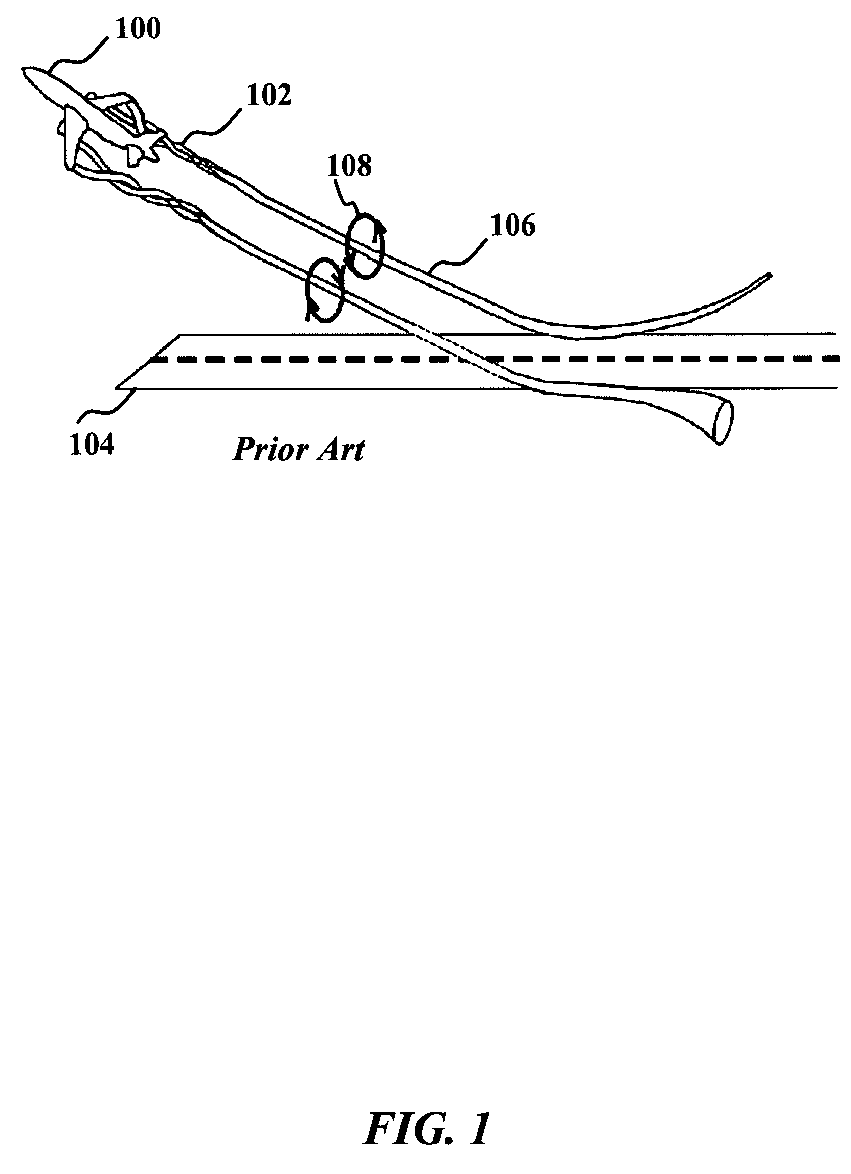
[0031]FIG. 1 shows a perspective view of a typical fixed-wing aircraft 100 generating a circulation 102 in the air flow in which it travels through as it lifts off from an airport runway 104. This circulation 102 results in discrete trailing vortices 106 that extend far behind the generating aircraft 100. For large aircraft 100, these trailing vortices 106 tend to be strong and persistent, such that they can pose a serious threat to any aircraft 100 that may encounter them. This problem is referred to as the wake vortex hazard, where the ...


PUM


Abstract

A wake vortex alleviator is provided. The wake vortex alleviator produces rapid variations in the position of vortices emanating from aerodynamic surfaces by using an active flap that moves span-wise back and forth along the outboard section of the surface. Rapidly moving the flap back and forth in a slot at an appropriate frequency will cause the vortex to oscillate, resulting in interaction between other vortices and subsequent destruction much earlier than it would occur naturally. The slot is positioned near the aerodynamic surface trailing edge and generally transverse to a chord line of the aerodynamic surface. The flap can be moved using a variety of actuators to position, translate and stow the flap. The oscillation frequency and position are guided by information feedback according variations in lift in the aerodynamic surface, such as wind gusts. The flaps can control yaw, roll and pitch of the aerodynamic surface.

Description

CROSS-REFERENCE TO RELATED APPLICATIONS[0001]This application is cross-referenced to and claims the benefit from U.S. Provisional Patent Application 60 / 791,787 filed Apr. 13, 2006, which is hereby incorporated by reference.FIELD OF THE INVENTION[0002]The invention relates generally to flaps on aircraft. More particularly, the invention relates to an active translating partial span flap to produce rapid variations in the position of vortices for causing early destruction of wake vortices thereby reducing the wake vortex turbulence hazard.BACKGROUND[0003]The goal in today's aviation market is to improve airport capacity. Heavy aircraft produce very strong vortices when flying at low speed during takeoff and landing, thus creating potential hazards for following aircraft. Consequently, the wake vortex hazard has become the limiting factor in airport capacity.[0004]Flying aircraft leave a system of vortices trailing behind as a necessary consequence of the generation of lift. For large ...

Claims


Application Information

Patent Timeline
Patent Type & Authority Patents(United States)
IPC IPC(8): B64C9/00
CPCB64C23/06Y02T50/162B64C2003/145Y02T50/10
Inventor EATON, JOHN K.MATALANIS, CLAUDE
Owner THE BOARD OF TRUSTEES OF THE LELAND STANFORD JUNIOR UNIV
Why Eureka
Try Eureka