
Control of optical connections in an optical network

a technology of optical connections and optical networks, applied in the field of optical communication, can solve the problems of sacrificing the simplicity and flexibility of the internet, sacrificing the scalability of the internet, so as to achieve efficient restoration of network service, simple optics, and enhanced ip layer

Inactive Publication Date: 2010-06-22
AT&T INTPROP II L P
View PDF4 Cites 7 Cited by
  • Summary
  • Abstract
  • Description
  • Claims
  • Application Information

AI Technical Summary

Benefits of technology

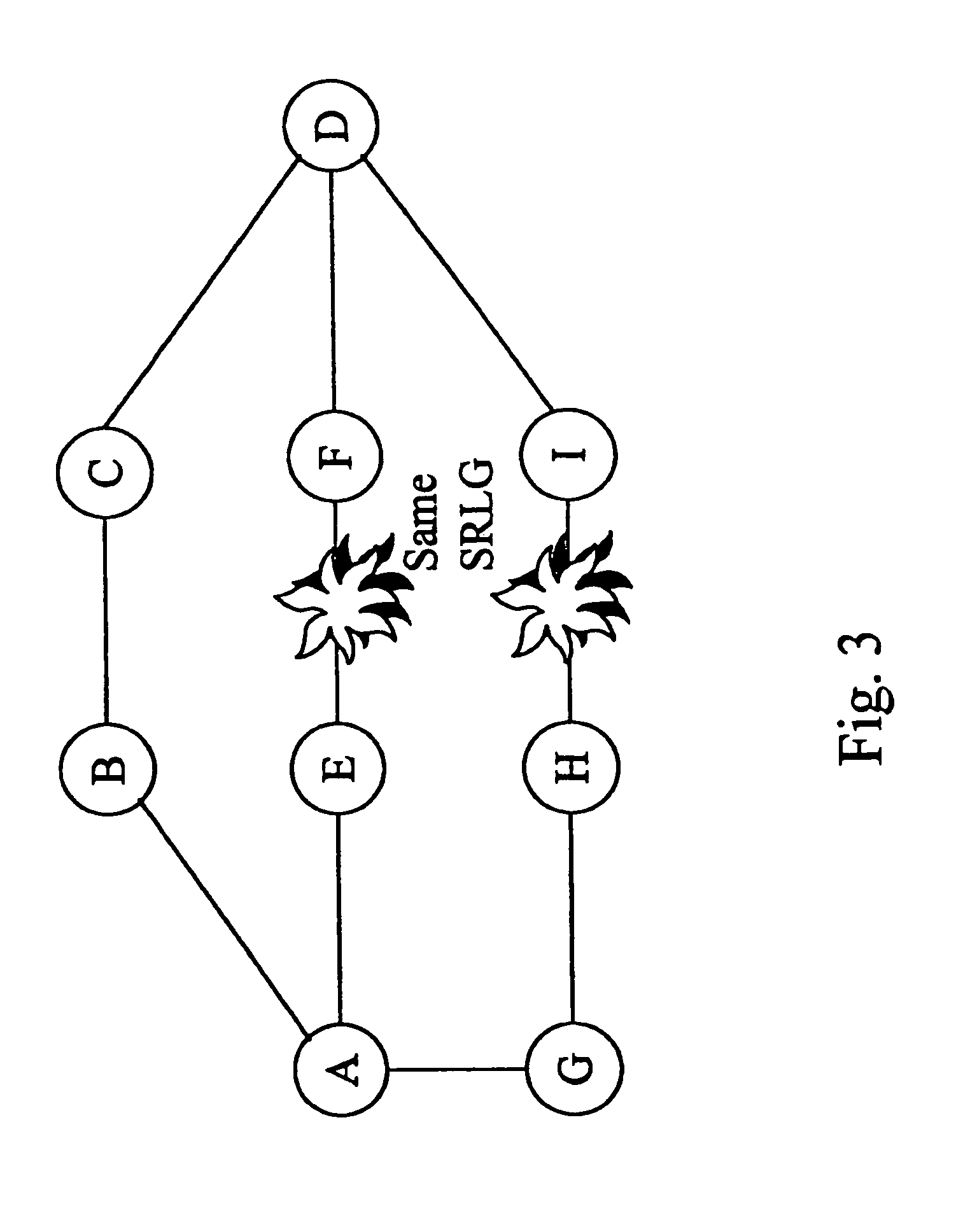
[0018]It is a further object of this invention to describe a smart router with simple optics and an enhanced IP layer as the basis for a novel combination IP router and OLXC. It is further an object of this invention to describe a method and system for restoration of service in the event of a failure in a fiber or set of fibers that have a shared risk of failure. In particular, it is an object of this invention to efficiently restore network service by pre-reserving bandwidth along routes that are physically diverse from the primary routes.

Problems solved by technology

However, the continuing high growth rate of Internet traffic volumes is becoming one of the Internet's most challenging scalability problems.
There is an underlying conflict, however, between the typical datagram (connectionless) service that supports the best-effort data delivery of the Internet and virtual circuit (connection-based) service.
The challenge in leveraging the new optical capabilities to enhance the Internet and other services is to manage the optical resources efficiently, without sacrificing the simplicity and flexibility of the Internet.
Whereas much of the transit capacity may carry IP traffic, operators leasing optical capacity may choose not to disclose this.
There are issues involving networks in general as they relate to where particular service and intelligence are provided.
Trying to run the Internet over an ATM network leads to redundancy of service at the transport layer which, for example, re-orders out-of-order packets as does the ATM layer.
This is inefficient at best.
Routing algorithms are another problem.
Non-adaptive routing algorithms are those routing algorithms that are static and do not adjust based on the traffic, queuing delays or environmental conditions such as failed components.
This points also to issues as to where the failure or failover mechanisms lie and the response time to invoke such mechanisms.
On the other hand, a similarly failed component in a connection-oriented network would lose all connections that passed through that component and even worse, it might take a significant amount of time for the source to discover the failure.

Method used


Image

  • Control of optical connections in an optical network
  • Control of optical connections in an optical network
  • Control of optical connections in an optical network

Examples


Embodiment Construction

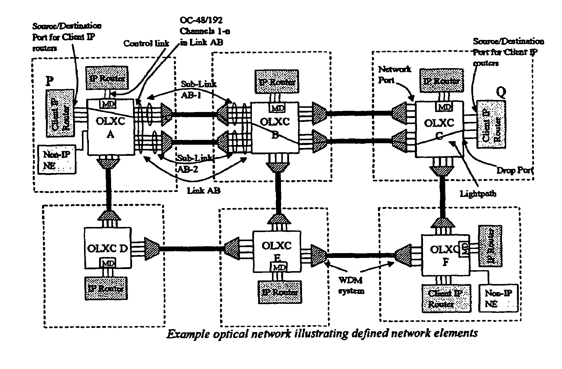
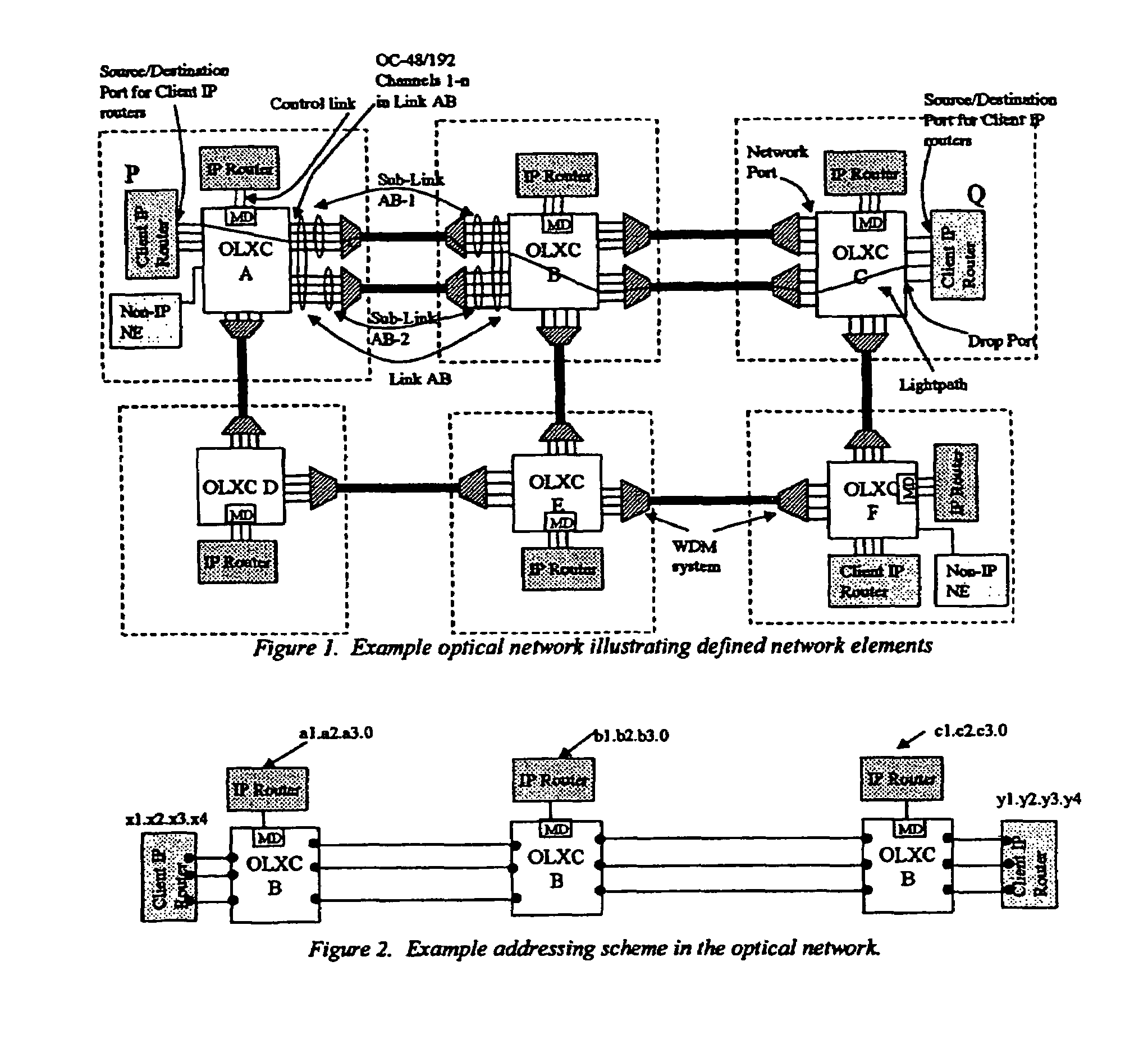
[0029]FIG. 1 illustrates an optical network with multiple optical layer cross-connects (OLXCs) interconnected via WDM links. Each node in this network consists of an IP router and a dynamically-reconfigurable OLXC. Optical lightpaths are established between network elements, via OLXCs. In FIG. 1 these network elements are client IP routers, illustrated at P and Q. A channel (or multiple channels) is chosen on each of the links along the route chosen for establishing a lightpath. Provisioning a lightpath is like establishing a connection using a connection setup mechanism. That is, a lightpath is like a virtual circuit.

[0030]In order to facilitate the description of the present invention the following network objects (also illustrated in FIG. 1) are defined. A Wavelength Division Multiplexer (WDM) is a system, which takes multiple optical inputs, converts them into narrowly spaced wavelength optical signals within an optical amplification band and couples them onto a single fiber. Th...


PUM


Abstract

A method for lightpath restoration in a reconfigurable optical network comprises the steps of naming each network addressable element in said reconfigurable optical network, determining current topology in said reconfigurable optical network, determining current resources in said reconfigurable optical network, requesting establishment of a lightpath, requesting reservation of restoration capacity, allocating the lightpath, and reserving the restoration capacity. Also disclosed is a method for lightpath restoration that comprises the steps of reserving restoration capacity, detecting transmission failures in the reconfigurable optical network, handling exceptions as a 10 result of transmission failures, and allocating transmission capacity.

Description

[0001]This application is a continuation of prior application Ser. No. 09 / 769,735 filed Jan. 26, 2001, now U.S. Pat. No. 7,039,009, which claims the benefit of U.S. Provisional Application No. 60 / 178,726, filed on Jan. 28, 2000, both of which are incorporated herein by reference.FIELD OF INVENTION[0002]The invention relates generally to optical communications and particularly to a method and system for the control and management of lightpaths in a reconfigurable optical network and for service restoration in the event of a failure, thereby improving network performance.BACKGROUND OF THE INVENTION[0003]The Internet is replacing the traditional telephone network as the ubiquitous network infrastructure. With its simple network interface and global reach, the Internet is already the target of almost all new network services. While experts debate on the exact growth rate of traffic volumes on the Internet, even by the most conservative estimates, packetized IP traffic will constitute mo...

Claims


Application Information

Patent Timeline
Patent Type & Authority Patents(United States)
IPC IPC(8): G01R31/08H04J14/02
CPCH04J14/0227H04J14/0283H04J14/0246H04J14/0287H04J14/0286H04J14/0295
Inventor CHAUDHURI, SIDHJALMTYSSON, GISLIYATES, JENNIFER
Owner AT&T INTPROP II L P
Learn More