

Microwindow device
a microwindow and window technology, applied in the field of image display system, can solve the problems of affecting the advantages and cost benefits of the microwindow device, the optics system is usually more complicated, and the inability to allow color sequential control, etc., and achieves the effect of simple optics, more compact size and cost-effectiveness
- Summary
- Abstract
- Description
- Claims
- Application Information
AI Technical Summary
Benefits of technology
Problems solved by technology
Method used
Image

Examples
Embodiment Construction
[0010]Therefore, one aspect of this invention is to disclose a new image display system with fast and bright transmissive display configuration to enable a display system implemented with a single device Color Sequential Control. The image display system has simpler optics and more compact size thus providing a more cost effective apparatus while achieving higher performance by displaying images with improved quality.
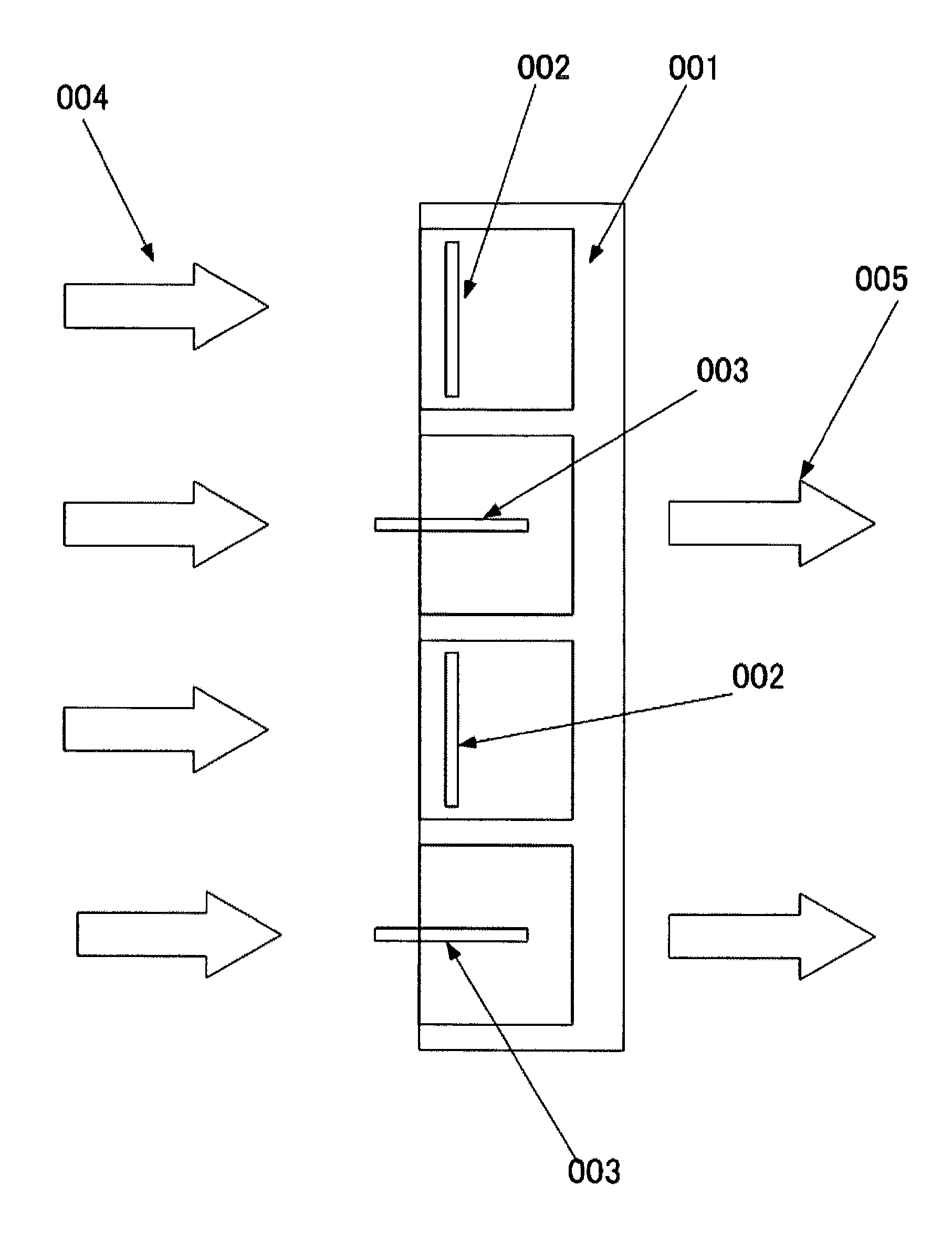
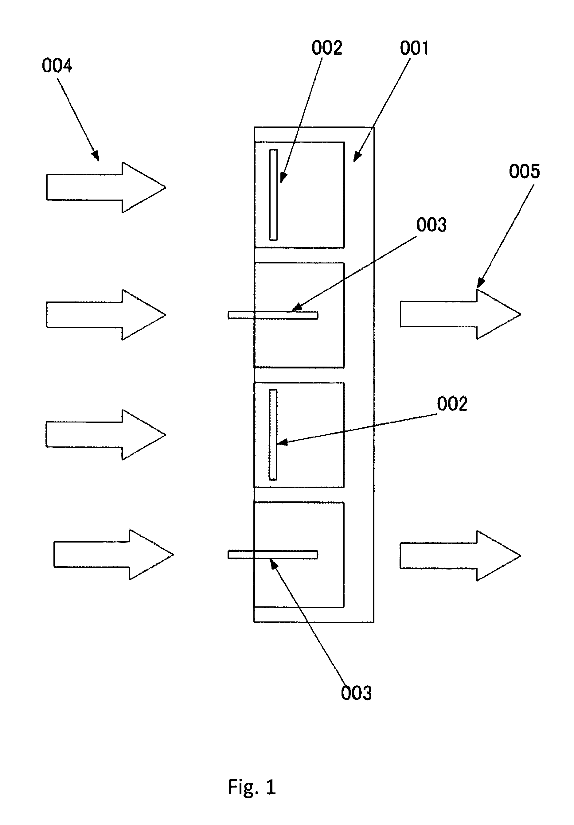
[0011]Specifically, it is an aspect of this invention that provides a new image display system with fast and bright transmissive display configuration by making and using movable micro-windows to operate in an open or close state for modulating and controlling the pixels to display color images with high speed control while reducing the overall size of the optical system.
[0012]While the novel features of the invention are set forth with particularly in the appended claims, the invention, both as to organization and content, will be better understood and appreciated, alo...
PUM
 Abstract
Description
Claims
Application Information