
Microwindow device

a microwindow and window technology, applied in the field of image display system, can solve the problems of affecting the advantages and cost benefits of the microwindow device, the optics system is usually more complicated, and the inability to allow color sequential control, etc., and achieves the effect of simple optics, more compact size and cost-effectiveness

Inactive Publication Date: 2012-04-12
ISHII FUSAO
View PDF7 Cites 3 Cited by
  • Summary
  • Abstract
  • Description
  • Claims
  • Application Information

AI Technical Summary

Benefits of technology

[0010]Therefore, one aspect of this invention is to disclose a new image display system with fast and bright transmissive display configuration to enable a display system implemented with a single device Color Sequential Control. The image display system has simpler optics and more compact size thus providing a more cost effective apparatus while achieving higher performance by displaying images with improved quality.
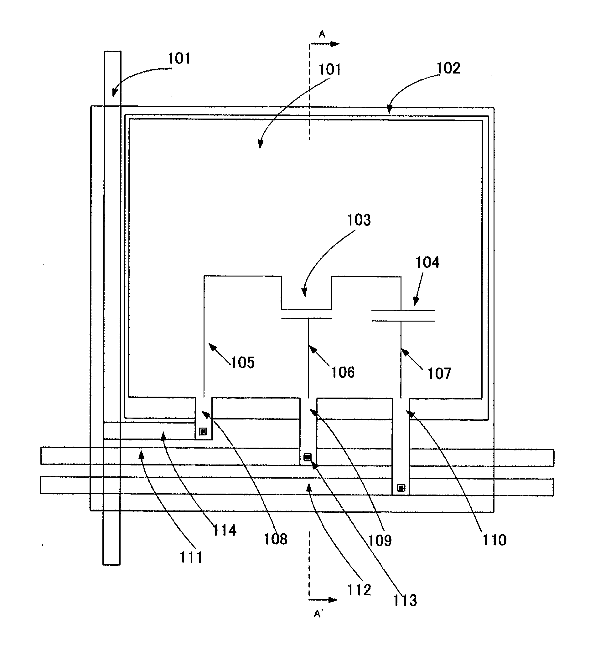
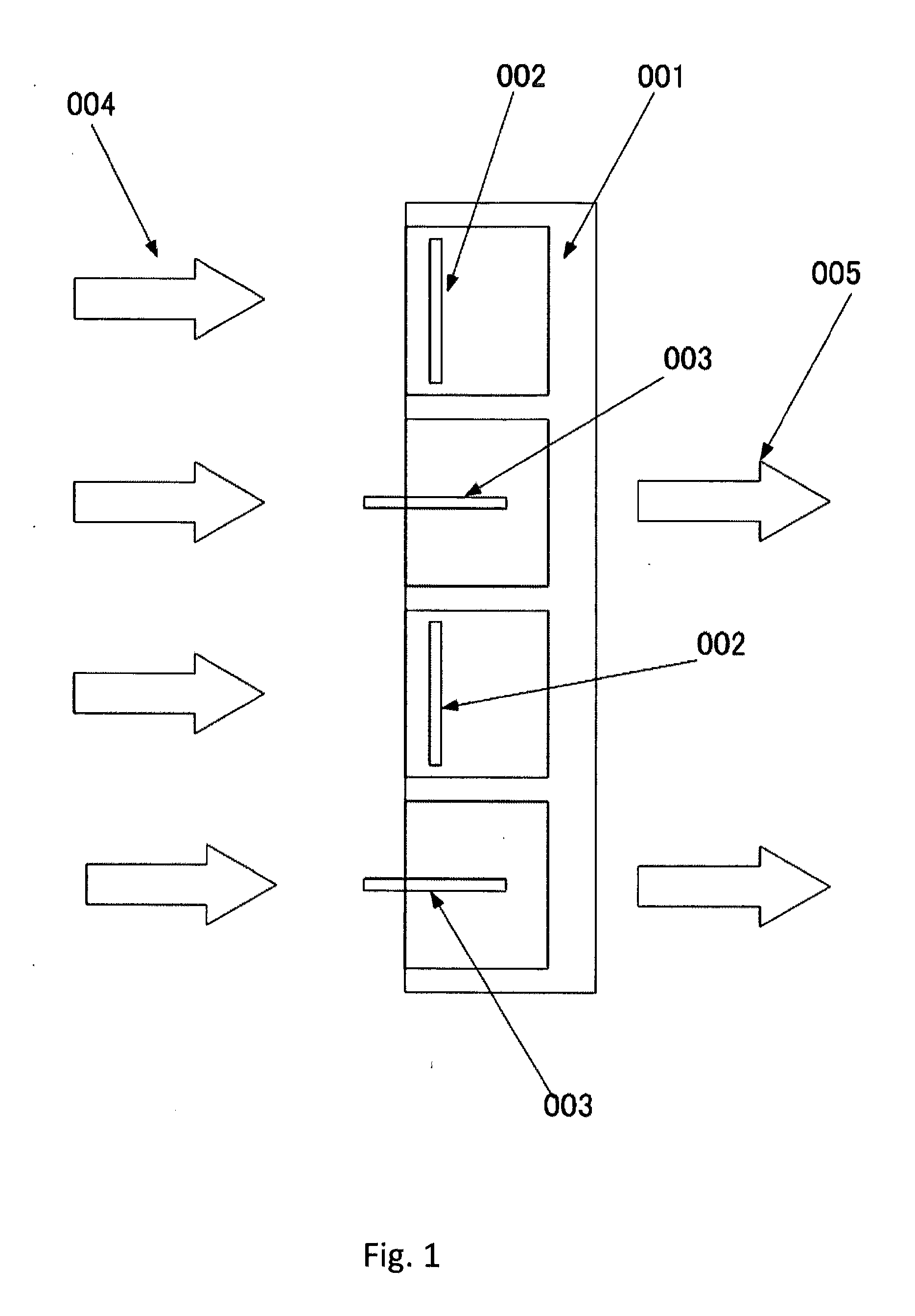
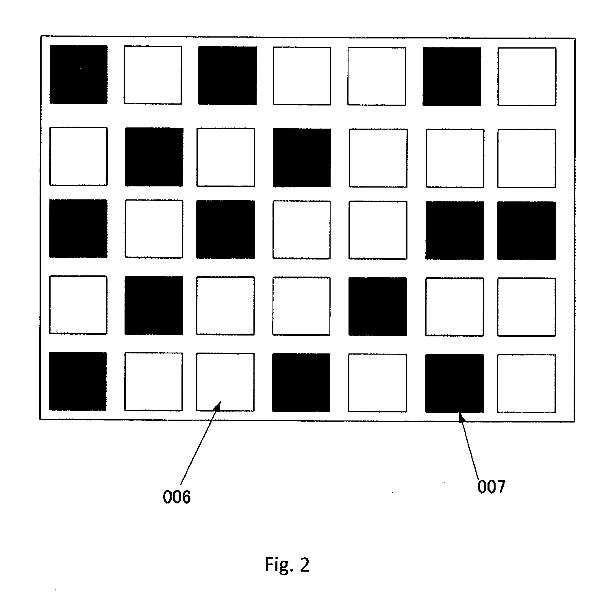
[0011]Specifically, it is an aspect of this invention that provides a new image display system with fast and bright transmissive display configuration by making and using movable micro-windows to operate in an open or close state for modulating and controlling the pixels to display color images with high speed control while reducing the overall size of the optical system.

Problems solved by technology

Additionally, due to the slow speed, the LCD image projection systems typically are required to implement three panels and do not allow for Color Sequential Control.
Even though the micromirror devices have significant advantages over the LCD systems, the optics systems are usually more complicated because of reflection systems rather than transmissive systems.
The advantages and cost benefits of the micromirror devices are adversely affected due to this requirement of a larger optical system when the reflective optical configuration is implemented.
In addition to the requirement of optics of larger size, the reflective display devices are further limited to application in the projection display apparatuses while the transmissive display systems have broader applications for implementation in the direct view and projection display systems, such as the LCD display systems.
However, such systems are limited by the fact that the structure cannot have more than 50% of opening due to its sliding door type structure.
However, this structure as that shown in FIG. 15B, requires high power to drive.

Method used


Image

  • Microwindow device
  • Microwindow device
  • Microwindow device

Examples


Embodiment Construction

[0010]Therefore, one aspect of this invention is to disclose a new image display system with fast and bright transmissive display configuration to enable a display system implemented with a single device Color Sequential Control. The image display system has simpler optics and more compact size thus providing a more cost effective apparatus while achieving higher performance by displaying images with improved quality.

[0011]Specifically, it is an aspect of this invention that provides a new image display system with fast and bright transmissive display configuration by making and using movable micro-windows to operate in an open or close state for modulating and controlling the pixels to display color images with high speed control while reducing the overall size of the optical system.

[0012]While the novel features of the invention are set forth with particularly in the appended claims, the invention, both as to organization and content, will be better understood and appreciated, alo...


PUM


Abstract

The present invention provides a transmissive Spatial Light Modulator with fast response speed and higher brightness using micro-windows having switching transistors on said window so that the fill factor of light transferring area can be maximized. Conventional systems have transistors out of windows which substantially reduce the area to pass incoming light, because transistors are usually opaque and block light transmission. Transmissive Spatial Light Modulator requires simpler and smaller optics than reflective Spatial Light Modulator.

Description

PRIORITY OF APPLICATION[0001]This Patent Application is a Non-provisional Application and claims the Priority Date of a co-pending Provisional Application 61 / 404,617 filed on Oct. 6, 2010 by a common Inventor of this Application. The Disclosures made in the Patent Application 61 / 404,617 are hereby incorporated by reference.BACKGROUND OF THE INVENTION[0002]The present invention relates to an image display system that modulates illumination light from a light source and displays two-dimensional images. More particularly, this invention relates to an image display system implemented with a spatial light modulator which modulates incoming light by opening and closing micro-windows configured as a two dimensional pixel array.[0003]After the dominance of cathode ray tube (CRT) technology in the display industry over the past 100 years, the Flat Panel Display (FPD) and Projection Display technologies are now gaining popularity because of a smaller form-factor of the display control system ...

Claims


Application Information

Patent Timeline
Patent Type & Authority Applications(United States)
IPC IPC(8): G02B26/00H01L33/08
CPCG02B26/023
Inventor ISHII, FUSAO
Owner ISHII FUSAO
Learn More