High-energy laser system intercepting a target and method thereof

a laser system and laser technology, applied in the field of high-energy laser systems, can solve the problems of high-energy laser beam form, wavefront distortion of each, and it is not possible to precisely intercept the target, and achieve the effects of simple optics, reduced reaction speed, and low manufacturing cos

Active Publication Date: 2015-07-07
KOREA ADVANCED INST OF SCI & TECH
View PDF13 Cites 1 Cited by
  • Summary
  • Abstract
  • Description
  • Claims
  • Application Information

AI Technical Summary

Benefits of technology

[0030]As described above, since the high-energy laser system intercepting the target according to the present invention amplifies and reflects the laser beam irradiated to the target by phase conjugate mirror, it is possible to compensate the wave-front distortions generated by the amplifier as well as the atmospheric disturbance, thereby exactly intercepting the target by using only passive components.
[0031]Further, since the high-energy laser system intercepting the target according to the present invention uses the passive component, it does not require any special technique, and also since it does not use a piezoelectric actuator or the like, it is not restricted in the reaction speed.
[0032]Furthermore, since the high-energy laser system intercepting the target according to the present invention has a simpler optics than the adaptive optics in the conventional intercepting apparatus, the manufacturing cost is low. And when considering general properties of the optics which is influenced by minute vibration, it is possible to embody more stabilized apparatus by the present invention.
[0033]Therefore, when the present invention is applied to a military laser system intercepting a target, it is expected to increase precision and efficiency of the target interception.

Problems solved by technology

One of problems in the conventional intercepting apparatus is to form the high energy laser beam which is mainly formed by amplifying and combining multiple laser beams.
A technical problem in combining the laser beams is to overcome wave-front distortion of each laser beam.
Another problem in the intercepting apparatus using the high energy laser beam is to irradiate the high energy laser beam to an exact position so as to intercept a target.
Since the atmospheric disturbance functions as an optical dispersive medium, the laser beam is distorted and refracted through the atmospheric disturbance, and thus it is not possible to exactly intercept the target.
And also the laser beam wave-front is to be distorted by the atmospheric disturbance and the intensity distribution becomes distributed widely at the target so that the damage on the target becomes very weak.
However, the adaptive optics has some disadvantages in that its response speed is restricted by the piezoelectric actuator, its manufacturing cost is too high, it is too bulky and heavy, and its operation is very complicated.
Furthermore, in order to measure and compensate the wave-front distortion using the wave-front sensor and the deformable mirror, the adaptive optics should have a very complicated construction even though it gives incomplete wave front compensation.
In other words, the conventional intercepting apparatus, which has the adaptive optics so as to solve the problem of failing the target interception due to the wave-front distortion and the light refraction when irradiating the high energy laser beam to the target, has a high manufacturing cost and a complicated driving mechanism.
Thus, it is difficult to stabilize the apparatus and the response speed is restricted.

Method used


Image

  • High-energy laser system intercepting a target and method thereof
  • High-energy laser system intercepting a target and method thereof
  • High-energy laser system intercepting a target and method thereof

Examples


Embodiment Construction

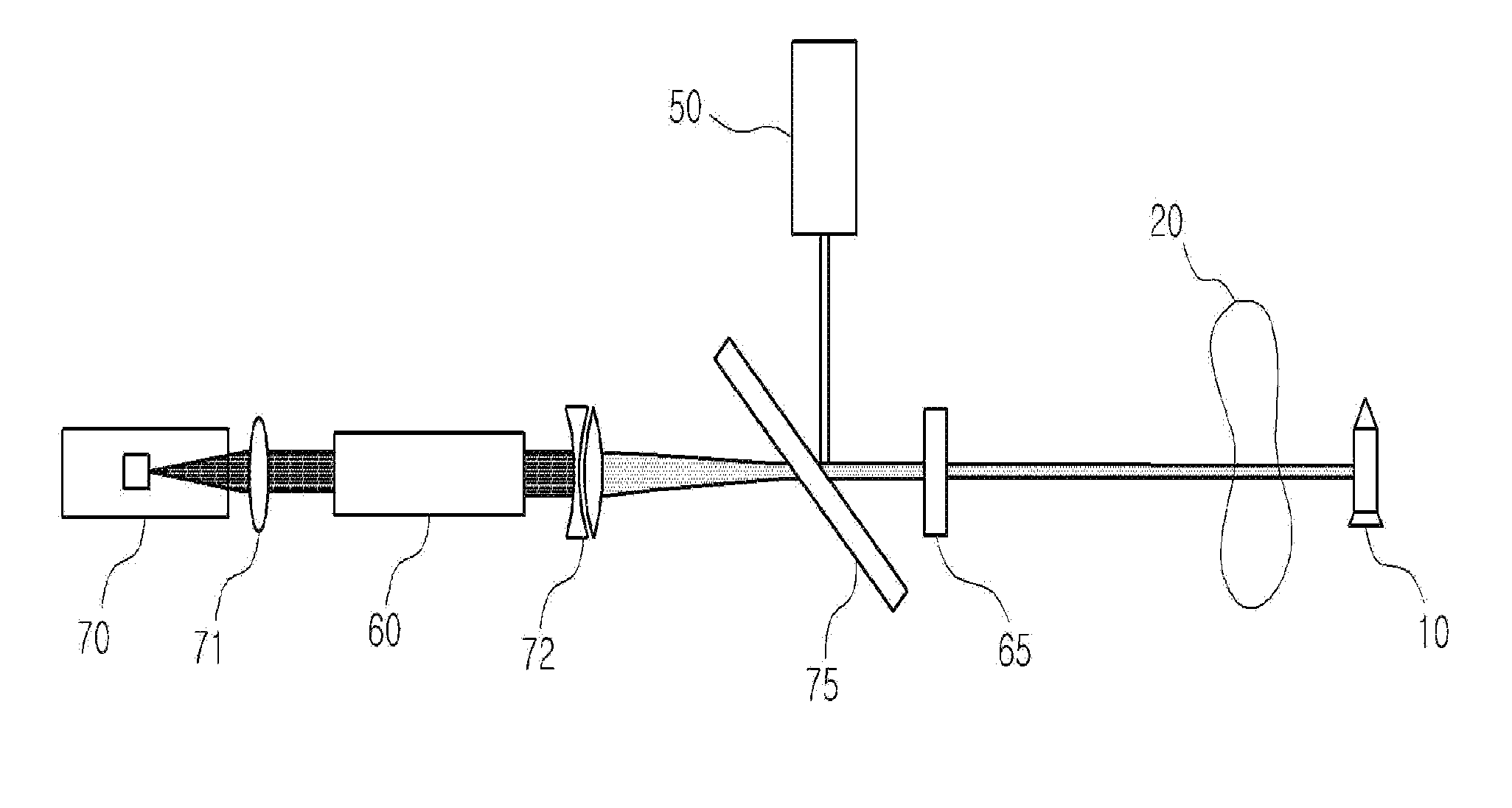
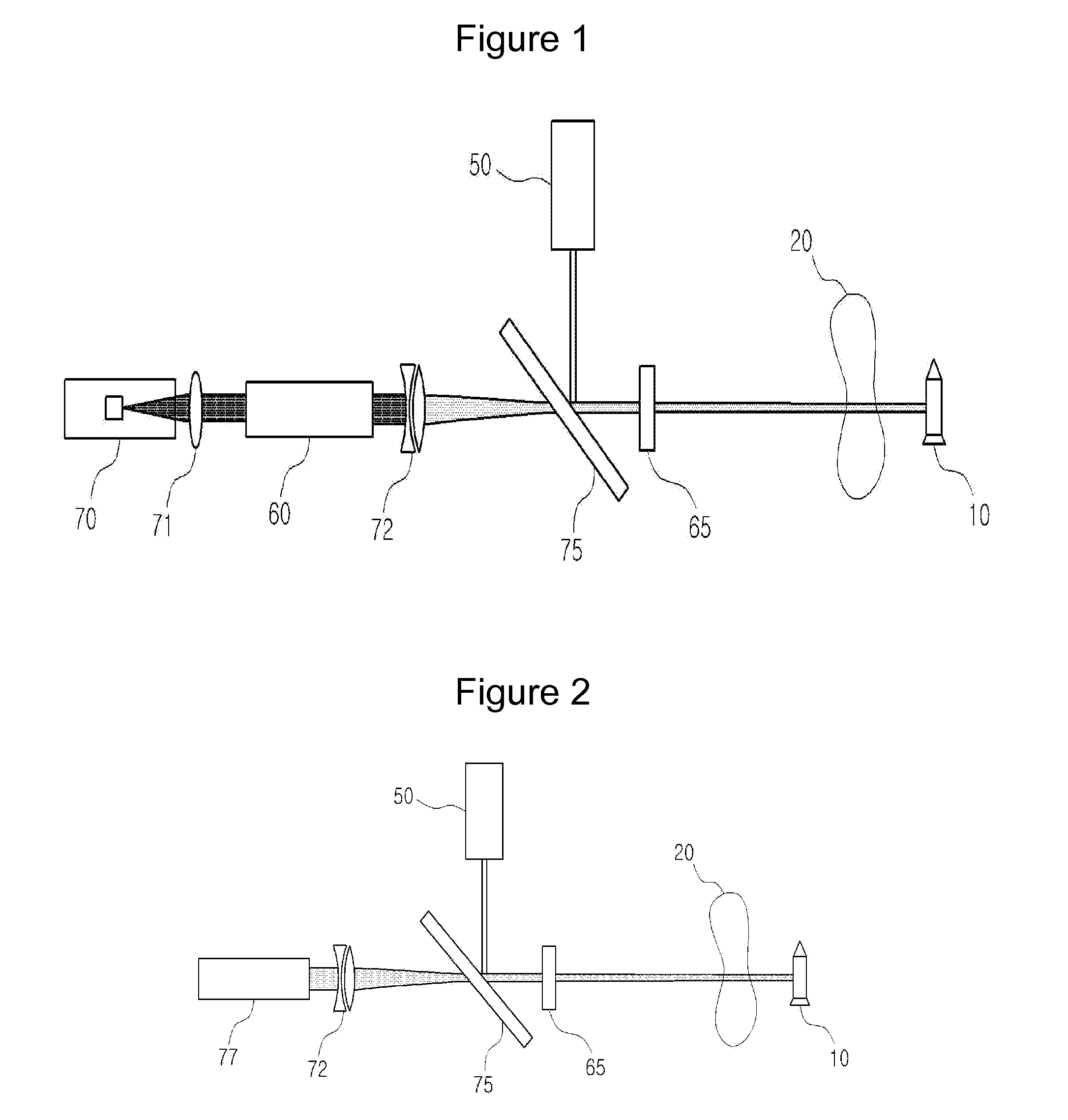
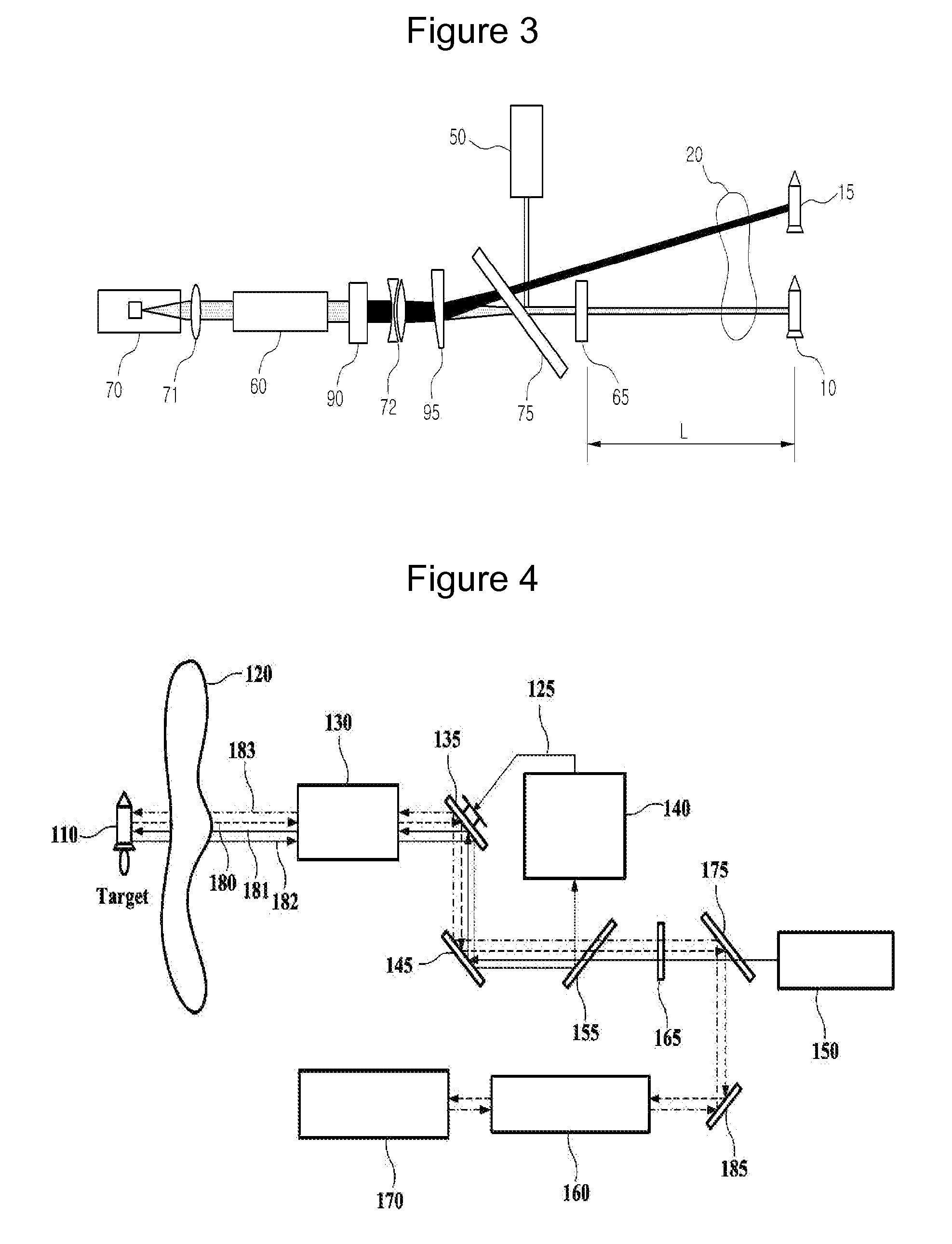
[0041]10, 110, 210: initial target position

[0042]15, 215: moved target position

[0043]20, 120, 220: atmospheric disturbance

[0044]130, 230: telescope 135, 235: aiming mirror

[0045]140, 240: target track sensor

[0046]145, 245: reflecting mirror

[0047]50, 150, 250: laser oscillator

[0048]155, 255: beam splitter 60: light amplifier

[0049]160, 260: serial light amplifier

[0050]65: polarization converter

[0051]165, 265: quarter wave plate

[0052]70, 170, 270: phase conjugate mirror

[0053]71, 72: irradiating lens

[0054]75, 175, 275: polarizing beam splitter

[0055]77: light amplifier using SBS-PCM

[0056]180, 280: irradiated laser beam scattered from target

[0057]181, 281: laser beam irradiated to target

[0058]182, 282: sunlight reflected from target

[0059]183, 283: high energy laser beam intercepting target

[0060]185, 285: reflecting mirror

[0061]90, 290: n-th order harmonic generator

[0062]95, 295: wedge-shaped glass plate

[0063]300: wedge-shaped glass plate having an angle β

[0064]320: laser beam having a freq...


PUM


Abstract

A high-energy laser system intercepting a target using a phase conjugate mirror includes a laser oscillator which generates a laser beam irradiated to the target, a light amplifier which receives the laser beam irradiated to and reflected by the target so as to amplify it, a phase conjugate mirror which reflects the amplified laser beam. And the laser beam that is reflected by the phase conjugate mirror is amplified again in the light amplifier, and then irradiated to the target so as to intercept the target.

Description

TECHNICAL FIELD[0001]The present invention relates to a high-energy laser system intercepting a target and a method thereof, which irradiates a laser beam to a target in the early stage, amplifies the laser beam scattered from the target using a phase conjugate mirror and an amplifier and then irradiates again the amplified beam to the target by using only passive components, thereby intercepting the target with very high accuracy.BACKGROUND ART[0002]For military purposes, there has been developed various laser technologies which intercepts a long-range mortar, a missile or the like from the air or ground. Recently, as a part of the MD (missile defense), USA has carried-out a successful experiment with the air borne laser test bed for intercepting a liquid-fueled ballistic missile launched from the ground.[0003]In a conventional apparatus for intercepting a missile or the like using laser, firstly, it was necessary to irradiate a tracking laser beam to the missile and to analyze vel...

Claims


Application Information

Patent Timeline
Patent Type & Authority Patents(United States)
IPC IPC(8): G01P3/36F41H13/00
CPCF41H13/0062
Inventor KONG, HONG JINSHIN, JAE SUNGPARK, SANG WOOSHIM, KANG SUPCHA, SEONG WOO
Owner KOREA ADVANCED INST OF SCI & TECH
Why Eureka
Try Eureka