Planning method and system for free-form implant modification

a free-form, bone implant technology, applied in the field of bone implants, can solve the problems of uneven bone removal, uneven bone removal, and inability to accurately plan the above method, so as to improve the planning and preparation of the bone.

Active Publication Date: 2010-06-22
SMITH & NEPHEW ASIA PACIFIC PTE LTD +2
View PDF9 Cites 172 Cited by
  • Summary
  • Abstract
  • Description
  • Claims
  • Application Information

AI Technical Summary

Benefits of technology

[0012]A difference between the above method and the prior art is that the planning method assists in producing a free-form area, and such a free-form area can be much more flexibly configured than prescribed, flat and / or straight planes that are achieved using cutting blocks. This increased configuration flexibility can save a great deal of functional bone material and, thus, this bone material is available in revision operations.
[0015]It is possible to form a counter area on the implant, corresponding to the free-form area on the bone. The method thus affords the advantage of automatically orientating the implant, since the free-form area already taken into account in the planning stage for the bone also can be automatically contoured as a counter piece in the implant. Such free-form areas enable an improved grip or hold between the implant and bone, a better load distribution due to the improved surface matching and / or modification, and as already mentioned, fewer complications in revision treatments. In addition, the free-form areas also can be modified to pre-contoured inner sides of implants.
[0022]a navigation-assisted bone ablating device that can ablate the bone on the free-form area.
[0026]The system and method can improve the planning and preparation of the bone for endoprosthetic implants. The prior art bone saw, which produces flat, planar portions, can be replaced by a different technology such as for example laser cutting, jet cutting, hybrid laser cutting or milling.

Problems solved by technology

The above method is very invasive, e.g., a great deal of bone material is ablated.
Moreover, the orientation of the implant often is not very accurate.
This improves the orientation of the implant, but smooth cuts still require significant bone removal.

Method used


Image

  • Planning method and system for free-form implant modification
  • Planning method and system for free-form implant modification
  • Planning method and system for free-form implant modification

Examples


Embodiment Construction

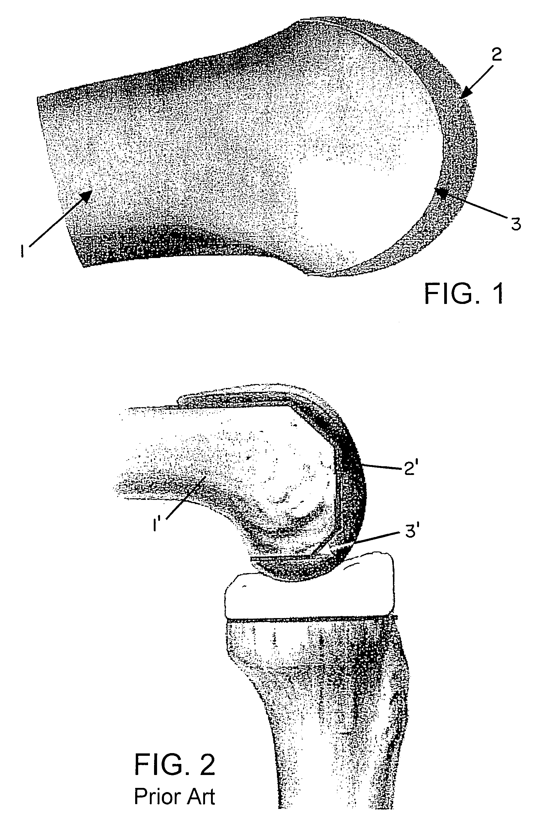
[0034]FIG. 1 shows a bone 1 wherein an implant 2 has been modified and attached to the bone. The exemplary implant 2 is configured to be round on its outer side, and its inner side has a form which is accurately modified to a free-form area 3 formed on the bone 1 based on a method described herein. It can be seen that the surface 3 of the bone 1 in the region of the implant 2 no longer consists of a sequence of smooth or flat planes, as has been the case in accordance with the prior art (see, e.g., FIG. 2), but rather exhibits a free form that shows bearing, healthy and functional bone material at each point on the surface 3. When comparing FIGS. 1 and 2, it can be seen that significant bone material is saved using the free-form method described herein relative to the prior art.

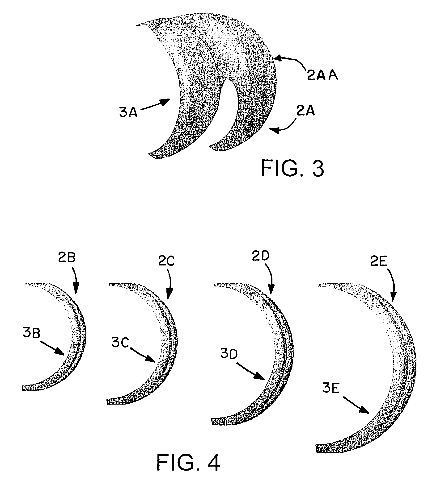
[0035]Although the free-form area 3 is shown as a curved area, the shape may be any shape that is conducive to retaining as much bone material as possible while providing a satisfactory support and bonding su...


PUM


Abstract

A method for planning a bone implant ascertains a condition of a bone to be treated, and identifies a dysfunctional part of the bone. A free-form area then can be ascertained and registered, wherein the free-form area lies below the dysfunctional part. A control data set then is produced that forms the basis for ablating the bone on the ascertained free-form area.

Description

RELATED APPLICATION DATA[0001]This application claims priority of U.S. Provisional Application No. 60 / 822,704 filed on Aug. 17, 2006, which is incorporated herein by reference in its entirety.FIELD OF THE INVENTION[0002]The invention relates to bone implants and, more particularly, to a planning method and system for modifying a bone and / or a bone implant.BACKGROUND OF THE INVENTION[0003]In order to provide a joint replacement in the human body, it is necessary to prepare the bone and / or implant such that a proper fit is achieved. Further, the implant must fulfil the requirements of bio-functionality and, therefore, must be accurately arranged and orientated.[0004]Prior to the availability of image-assisted or navigation-assisted surgery, the only way to orientate an implant was to predefine its modification by producing five planes with the aid of different positioning instruments such as, for example, an intramedullary pin. This technique is illustrated in FIG. 2, which shows a bo...

Claims


Application Information

Patent Timeline
Patent Type & Authority Patents(United States)
IPC IPC(8): A61B5/05A61B6/00G06G7/48
CPCG06F19/3437A61B19/22A61B19/52A61B19/5244A61F2/30942A61F2/3859A61B5/1077A61B17/1675A61B19/2203A61B19/50A61B2019/508A61B2019/5255A61F2002/30616A61F2002/3096A61F2002/4632A61B6/03A61B90/36A61B2034/2055A61B34/20A61B34/70A61B34/30A61B34/10A61B2034/108G16H50/50
Inventor NEUBAUER, TIMOMILLAHN, MANUEL
Owner SMITH & NEPHEW ASIA PACIFIC PTE LTD
Why Eureka
Try Eureka