
System and method of controlling data center resources for management of greenhouse gas emission

a data center and resource management technology, applied in adaptive control, process and machine control, instruments, etc., can solve the problems of significant power consumption of a data center, single high-density server rack,

Inactive Publication Date: 2010-06-22
CA TECH INC
View PDF21 Cites 64 Cited by
  • Summary
  • Abstract
  • Description
  • Claims
  • Application Information

AI Technical Summary

Benefits of technology

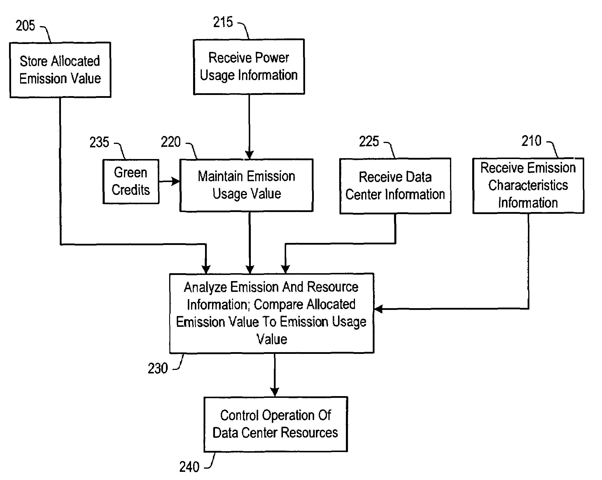
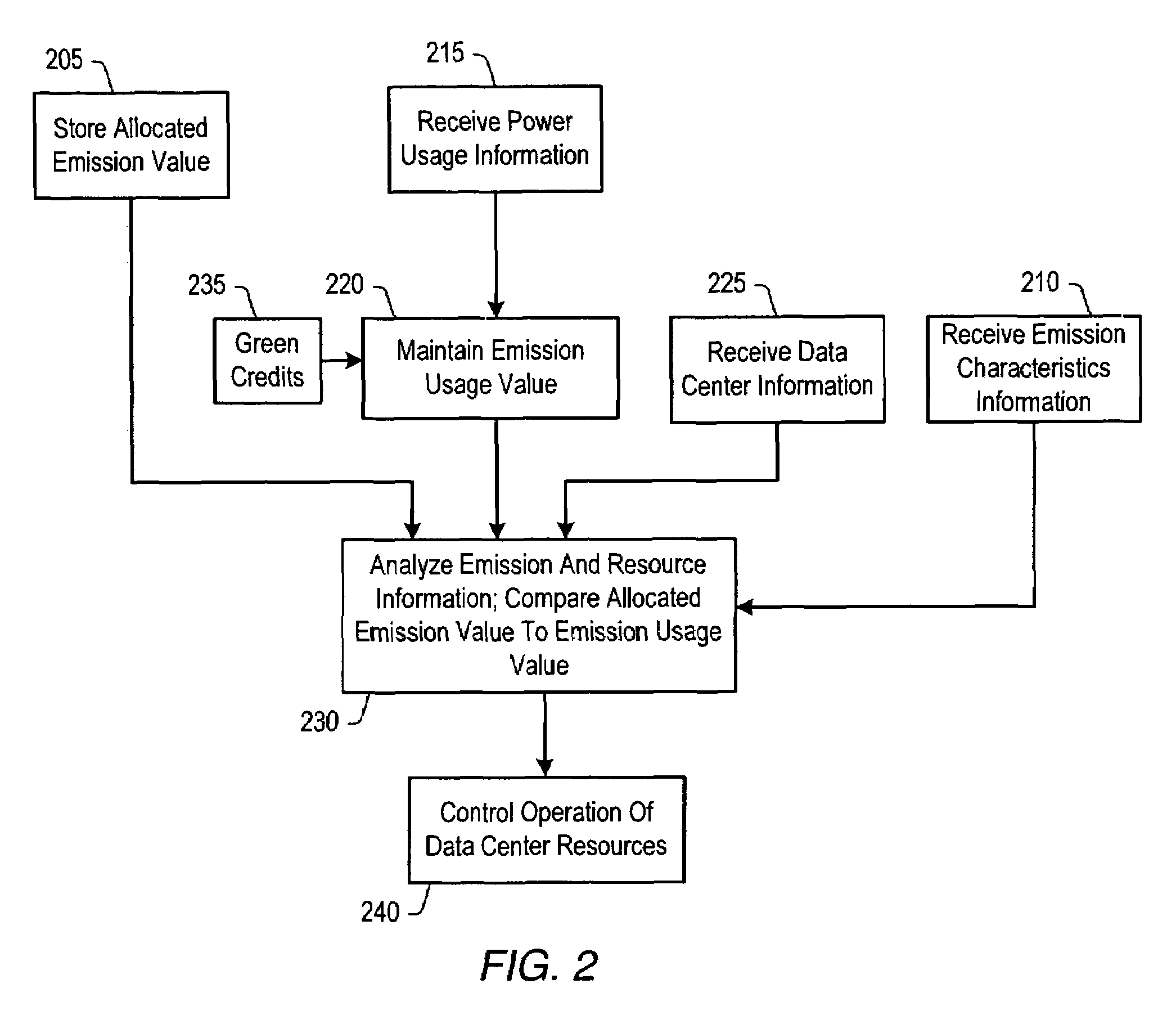
[0010]The data center control system may analyze some or all of the information to control the resources within the data center(s). For example, the control system may reschedule processing tasks or cause processing tasks performed on one or more computing resources to be performed on different computing resources within the data center. In addition, the control system may reduce power to one or more computing resources and / or the corresponding infrastructure systems within the data center. Further, the control system may reschedule processing tasks or cause processing tasks performed on one or more computing resources within one data center to be performed on computing resources to within a different data center.

Problems solved by technology

According to some studies done in conjunction with the United States Environmental Protection Agency (EPA), estimates indicate that a single high-density server rack may consume as much as 20 kW.
Thus, the power consumed by a data center is significant.
As energy costs rise, regional energy demand increases, and regulation of greenhouse gas emission increases, energy consumption and resource management may become a critical factor in managing a data center.
Further, the control system may reschedule processing tasks or cause processing tasks performed on one or more computing resources within one data center to be performed on computing resources to within a different data center.

Method used


Image

  • System and method of controlling data center resources for management of greenhouse gas emission
  • System and method of controlling data center resources for management of greenhouse gas emission
  • System and method of controlling data center resources for management of greenhouse gas emission

Examples


Embodiment Construction

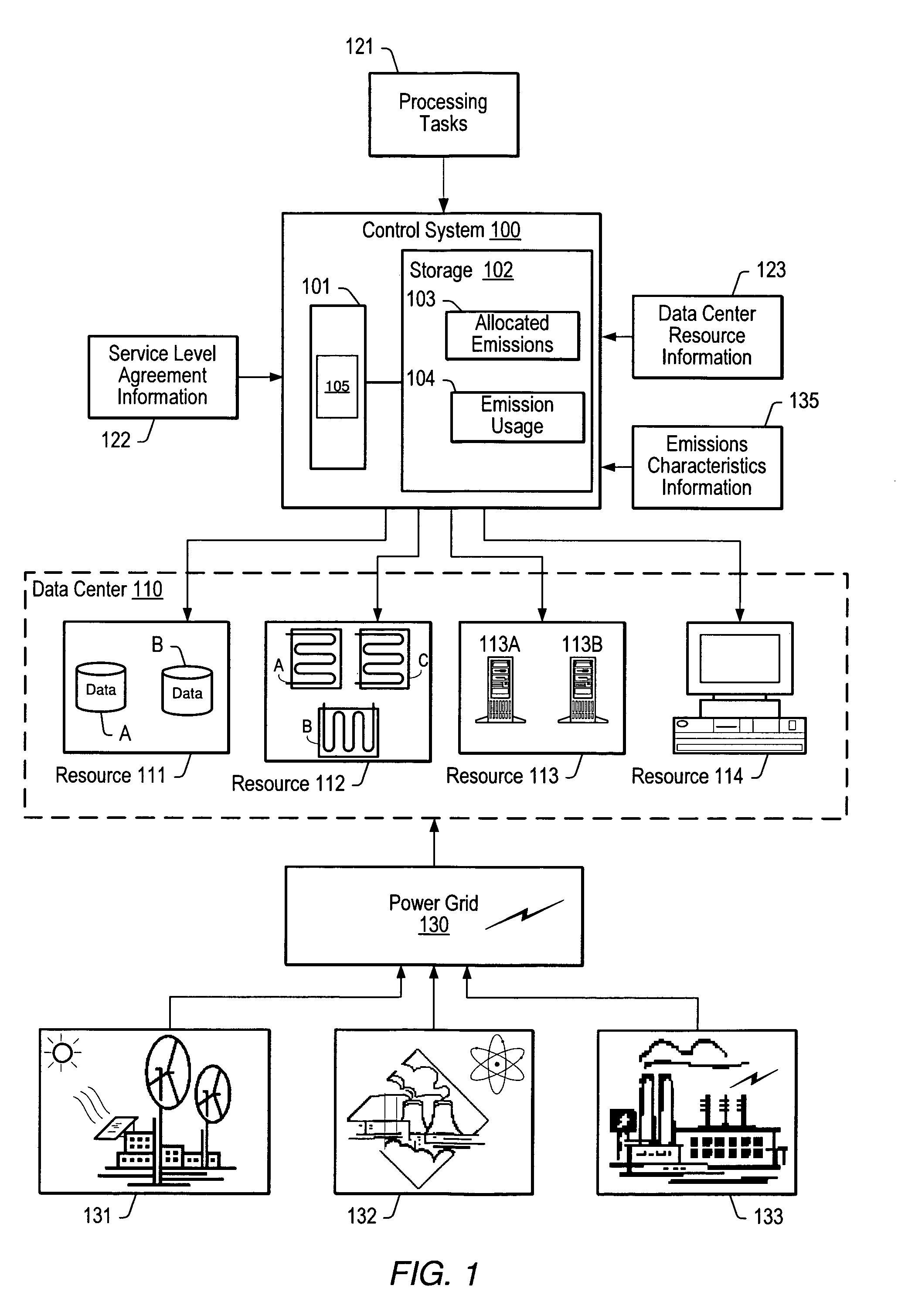
[0016]Turning now to FIG. 1, a diagram of one embodiment of a system for controlling data center resources is shown. The system includes a control system 100 which is coupled to various resources 111-114 within data center 110. Control system 100 may receive information corresponding to processing tasks 121 that may be performed in the data center. Control system 100 may also receive additional information. For example, in the illustrated embodiment, control system 100 may receive service level agreement information 122 that may be associated with one or more of the processing tasks 121, data center resource information 123, and emission characteristics information 135 that may be associated with one or more power generation facilities 131-133 that may generate the power that supplies the data center 110.

[0017]In the illustrated embodiment, data center 110 is coupled to a power grid 130. Power grid 130 may be representative of a typical electric power grid used to distribute power t...


PUM


Abstract

A data center control system includes a storage configured to maintain an emission usage value indicative of an estimated amount of greenhouse gas emission caused by consumption of power by resources within one or more data centers. The control system also includes a controller that may provide a signal to control an operation of at least one of the resources depending upon the indication of the estimated amount of greenhouse gas emission.

Description

BACKGROUND OF THE INVENTION[0001]1. Field of the Invention[0002]This invention relates to data center workload management and, more particularly, to the controlling of resources within data centers. The invention also relates to the regulation of greenhouse gases.[0003]2. Description of the Related Art[0004]For some time now, the task of addressing global warming has been gaining worldwide momentum. In an effort to curb global warming, many nations have begun instituting regulations on how much greenhouse gas an entity may emit. In some cases, these regulations stem from worldwide treaties that mandate a nation's maximum emissions. For example, an update to the United Nations Framework Convention on Climate Change (known as “the Kyoto Protocol”) has set mandatory emission limits for signatory nations. As such, a governing body within such a nation may provide an allocation of emissions (or amount of allowable emissions) to a given company. In addition, in non-signatory nations, vari...

Claims


Application Information

Patent Timeline
Patent Type & Authority Patents(United States)
IPC IPC(8): G05B13/02G06Q40/00G06F15/173
CPCG06F9/4843G06F9/4893G06Q40/04G06Q10/06Y02B60/144Y02P90/84Y02D10/00
Inventor BOTES, PAR
Owner CA TECH INC
Learn More