
System and method for detection of rotor eccentricity baseline shift

a rotor eccentricity and baseline shift technology, applied in the field of steam turbine monitoring, can solve problems such as rotor eccentricity differences and excessive reporting of rotor eccentricity changes

Inactive Publication Date: 2010-06-22
GENERAL ELECTRIC CO
View PDF12 Cites 37 Cited by
  • Summary
  • Abstract
  • Description
  • Claims
  • Application Information

AI Technical Summary

Benefits of technology

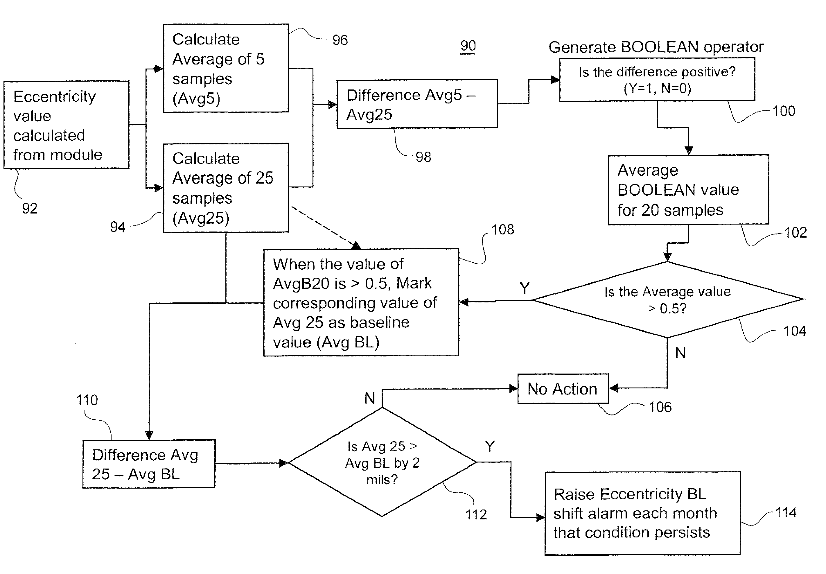
"The patent describes a method and system for determining the eccentricity of a rotor in a turbine. This is important for ensuring the rotor operates correctly and efficiently. The method involves collecting sensor data of rotor eccentricity during startup operations and using this data to establish a baseline eccentricity value. Thereafter, sensor data is filtered to select only data corresponding to startup operations, and the method calculates the difference between the baseline eccentricity value and the eccentricity values of each subsequent startup operation. This difference is reported as the rotor eccentricity condition. The system includes a rotor eccentricity sensor, a computer system with data filters and algorithms for establishing the baseline eccentricity value and determining the difference between subsequent startup operations, and a report generator for generating the rotor eccentricity condition. The technical effect of this patent is to provide a reliable and accurate means for determining rotor eccentricity in a turbine, which can help improve operational efficiency and prevent damage to the rotor."

Problems solved by technology

The method may also report a trend of the rotor eccentricity differences for a period of time of at least one year and reporting excessive changes in rotor eccentricity.

Method used


Image

  • System and method for detection of rotor eccentricity baseline shift
  • System and method for detection of rotor eccentricity baseline shift
  • System and method for detection of rotor eccentricity baseline shift

Examples


Embodiment Construction

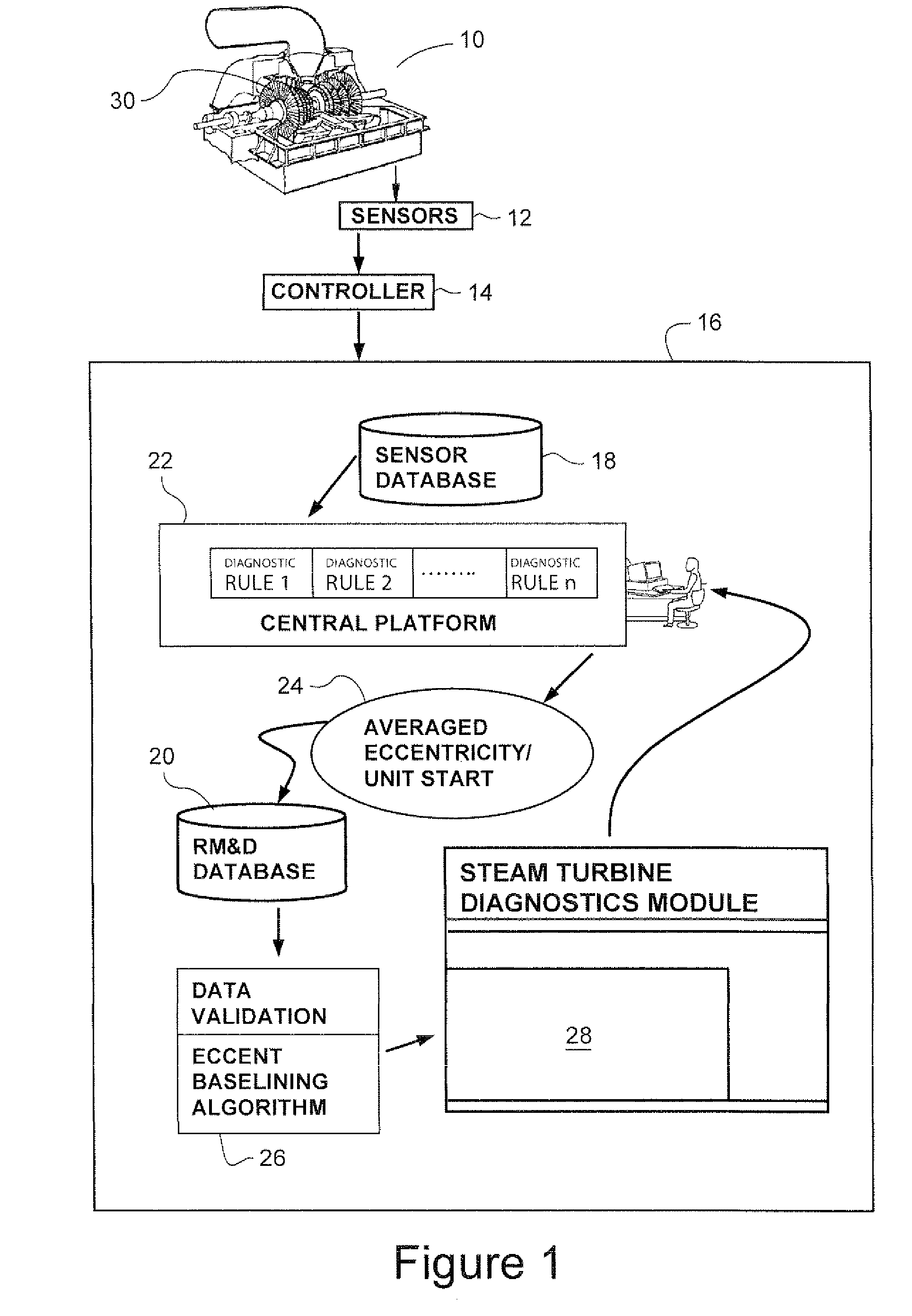
[0013]FIG. 1 is a schematic diagram of a steam turbine 10 monitored by a plurality of sensors 12, e.g., a displacement probes. Data from the sensors is received by a computer controller 14 for the steam turbine. The steam turbine 10, arrangement of the sensors 12, monitoring the turbine and turbine controller 14 are conventional and well-known components operating in a customary manner.

[0014]The sensors 12, e.g., displacement probes adjacent a turbine rotor 30, are commonly used for eccentricity monitoring and measurement on steam turbines. Displacement probes, data obtained from the sensors is routed through a local onsite monitor and stored on a central sensor database 18.

[0015]Data, e.g., eccentricity values and times at which the values are captured from sensor, is generated by the eccentricity monitoring sensors 12. The data may be relatively continuously captured by the sensors, such as every five minutes during the operation of the steam turbine. The controller 14 may store s...


PUM


Abstract

A method to determine eccentricity of a rotor in a turbine including: collecting sensor data of rotor eccentricity for a plurality of startup operations; establishing a baseline eccentricity value using the sensor data corresponding to a selected startup operation; determining an eccentricity value using the filtered sensor data for each of a plurality of startup operations subsequent to the selected startup operation; determining a rotor eccentricity difference between the baseline eccentricity value and each of the eccentricity values for the plurality of startup operations subsequent to the selected startup operation, and reporting a rotor eccentricity condition based on the rotor eccentricity difference.

Description

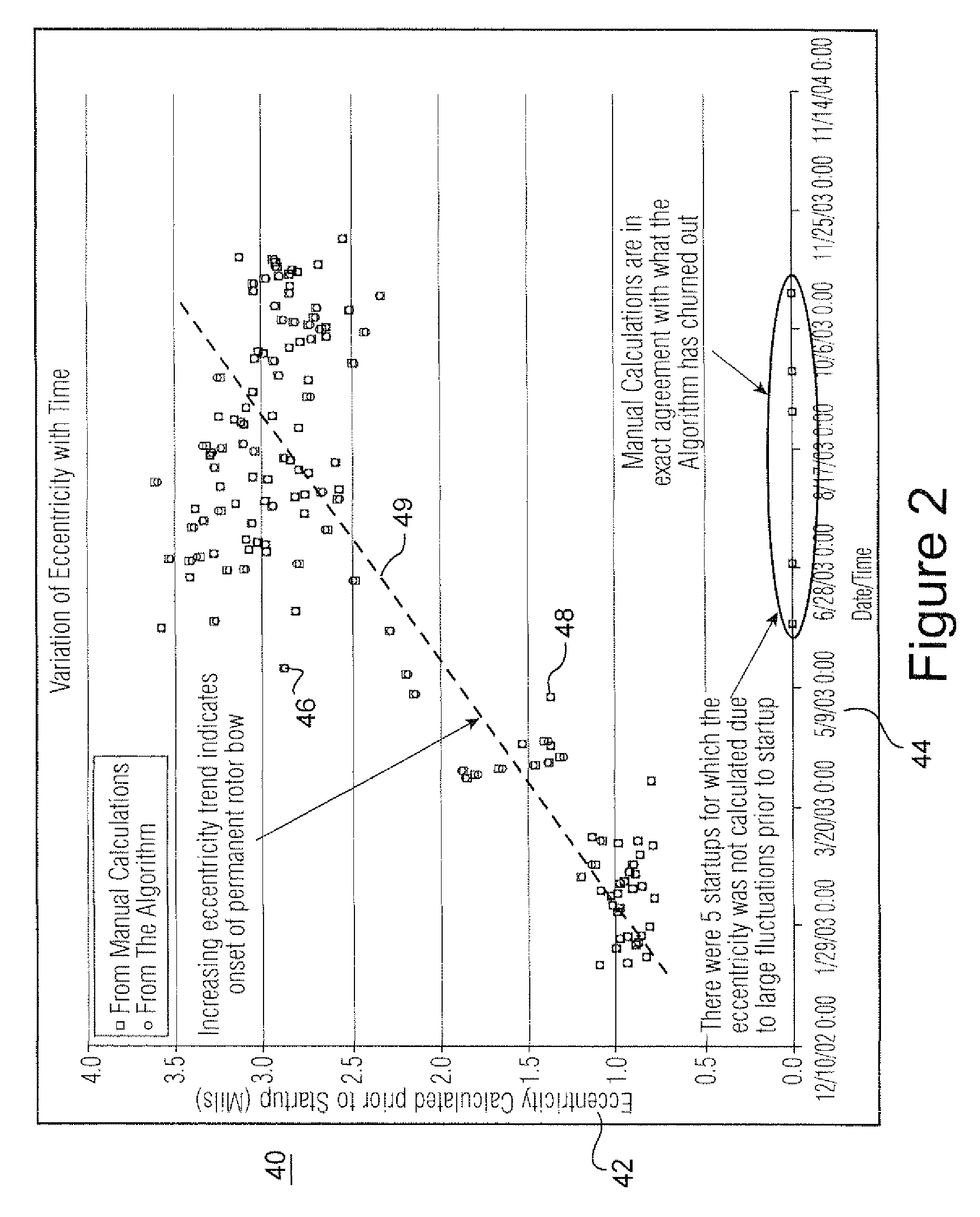
BACKGROUND OF THE INVENTION[0001]The present invention relates to steam turbines and, in particular, to monitoring eccentricity in the rotor of steam turbines.[0002]The eccentricity of a rotor in a steam turbine is an indicator of the bowing of the rotor shaft and is generally indicative of the vibratory condition of the turbine during transient and steady state operations. The amount of eccentricity in a turbine rotor has a significant impact on the availability, reliability, performance and operational life of a turbine rotor.[0003]Frequent steam turbine startups and shutdowns, which is common in combined steam turbine and gas turbine cycle units, tend to increase rotor eccentricity. An increase in eccentricity beyond a predetermined threshold limit indicates a permanent bow in the rotor. Excessive rotor bow typically results in rotor unbalance, which causes vibration of the rotor, and may lead to rubs between the rotating components and the stationary components of a steam turbin...

Claims


Application Information

Patent Timeline
Patent Type & Authority Patents(United States)
IPC IPC(8): G01B21/20G01B21/00G06F19/00
CPCF01D5/027F01D25/285F01D25/04
Inventor MURALIDHARAN, VASANTHKANT, ABHAY SUDHAKARRAOSARAVANAPRIYAN, S. N. ARULBALASUBRAMANIAM S B, MAHALAKSHMIKUMAR, JITENDRA
Owner GENERAL ELECTRIC CO
Learn More