Sound absorbing structure

a technology of sound absorption and structure, which is applied in the direction of electric apparatus casings/cabinets/drawers, instruments, transportation and packaging, etc., can solve the problems of increased thickness limited indoor space, and increased size of sound absorption structure, so as to achieve enhanced sound absorption capability in a band which includes resonance frequency and frequencies near the resonance frequency, and further enhanced sound absorption capability

Active Publication Date: 2010-06-29
PANASONIC CORP
View PDF40 Cites 46 Cited by
  • Summary
  • Abstract
  • Description
  • Claims
  • Application Information

AI Technical Summary

Benefits of technology

[0044]According to the fifteenth aspect described above, in the case where the sound absorbing structure is used, for example, as a sound absorbing wall installed in the vicinity of a noise source such as a road, a railroad, a factory or the like, a physical adsorption effect of the gas adsorption material is maintained for a long period even in a circumstance where there exist a number of substances reducing the physical adsorption effect of the gas adsorption material.
[0045]According to the seventeenth aspect describe

Problems solved by technology

As described above, there has been a problem that in order to lower the resonance frequency f0, the size of the sound absorbing structure is required to be increased or the thickness of the sound absorbing structure is required to be increased.
Also, in the case where the sound absorbing str

Method used


Image

  • Sound absorbing structure
  • Sound absorbing structure
  • Sound absorbing structure

Examples


first embodiment

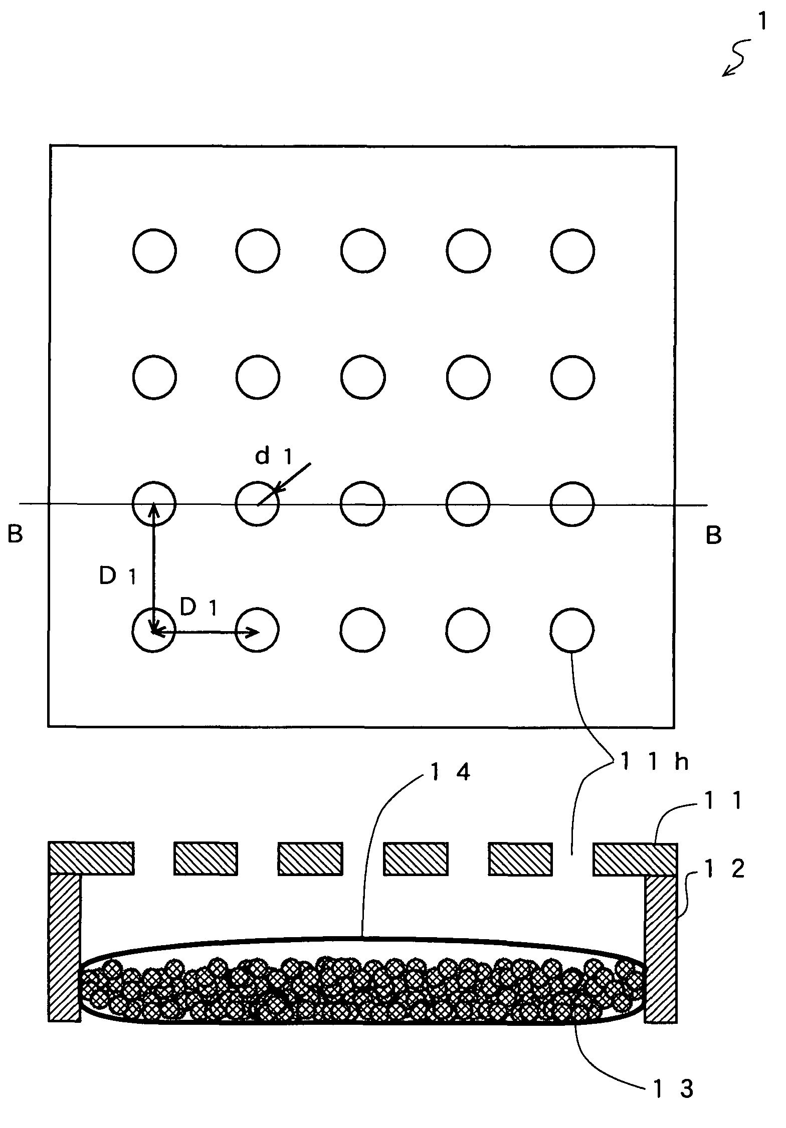
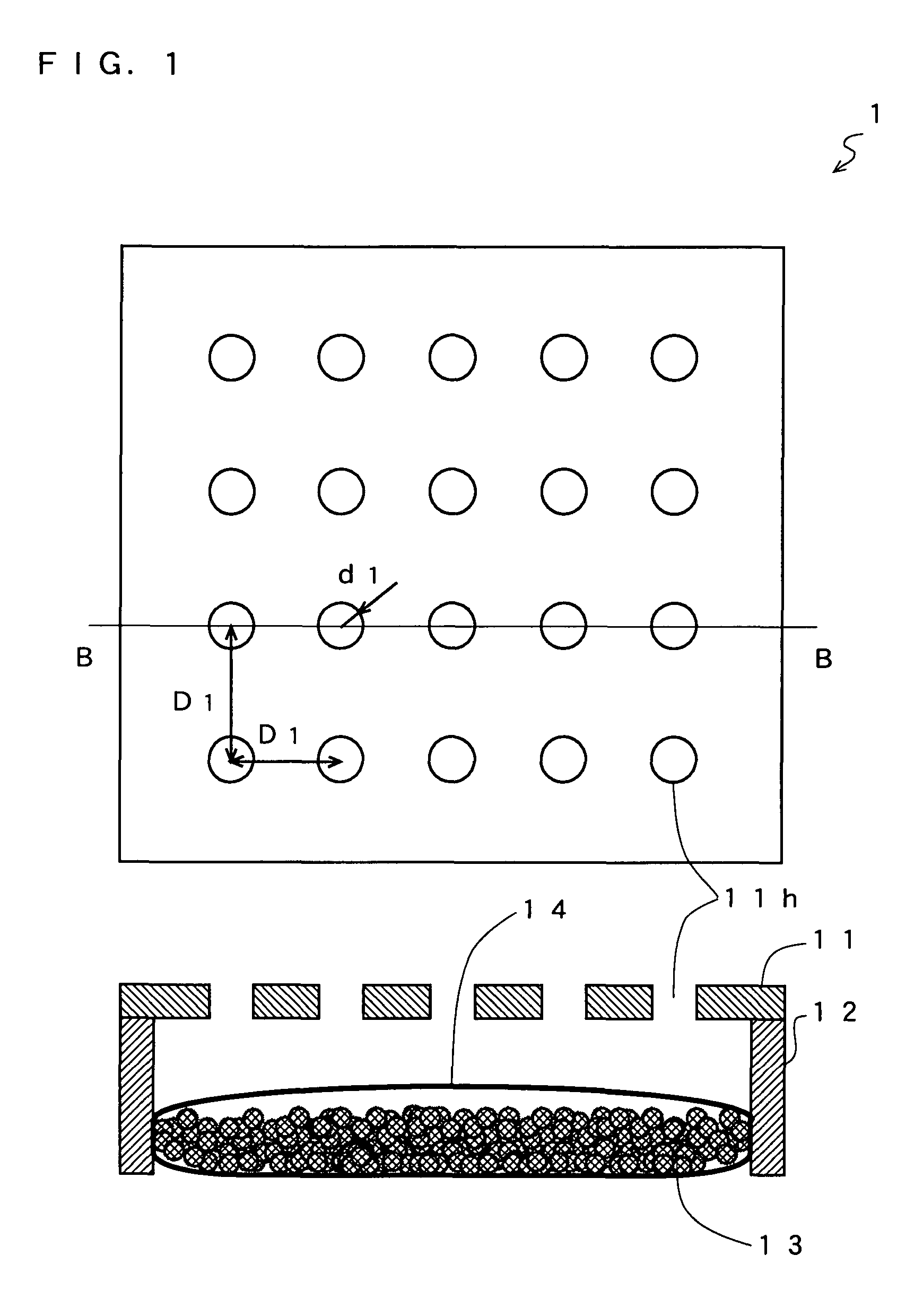
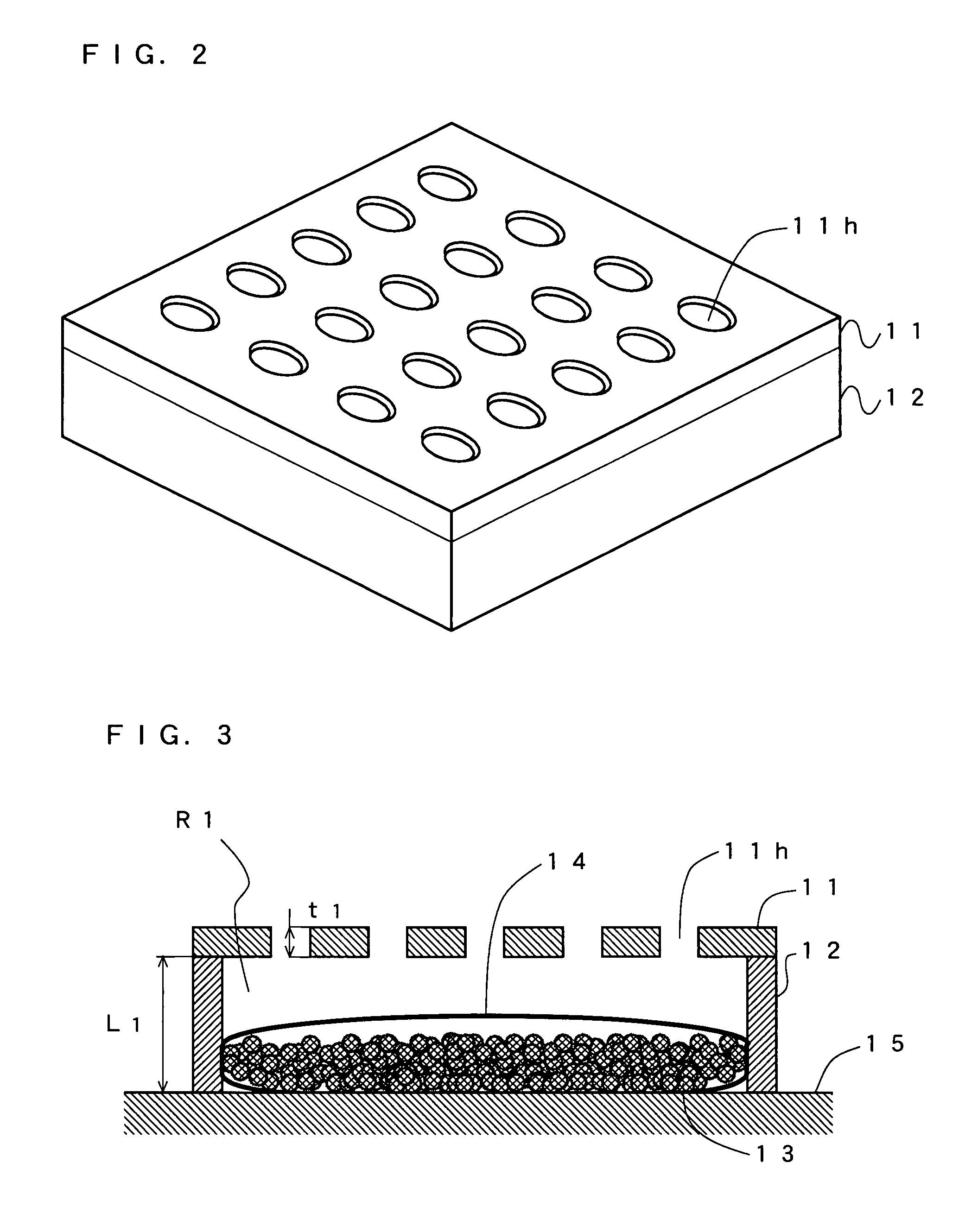
[0082]First, a sound absorbing structure 1 according to a first embodiment of the present invention will be described with reference to FIGS. 1 to 3. FIG. 1 shows a front view of the sound absorbing structure 1 and a cross-sectional view, taken along a line BB, of the sound absorbing structure 1. FIG. 2 shows a perspective view of the sound absorbing structure 1. FIG. 3 is a cross sectional view showing a structure of the sound absorbing structure 1 installed on a wall 15.

[0083]As shown in FIG. 1, the sound absorbing structure 1 comprises a front board 11, side boards 12, a gas adsorption material 13 and a shielding element 14. The front board 11 is a plate-like element such as a plywood plate, a hard fiberboard plate made of plaster or the like, a metal plate, and so on. In FIG. 1, a front surface of the front board 11 is square-shaped by way of example. In the front board 11, a plurality of openings 11h are formed. A shape of each opening 11h is, for example, round or slit-shaped....

second embodiment

[0112]A sound absorbing structure 2 according to a second embodiment of the present invention will be described with reference to FIG. 12. FIG. 12 is a cross-sectional view showing an exemplary structure of the sound absorbing structure 2. The sound absorbing structure 2 comprises a front board 21, side boards 22, a back board 26, an acoustic port 27, the gas adsorption material 13 and the shielding element 14. The sound absorbing structure 2 according to the present embodiment differs from the sound absorbing structure 1 described in the first embodiment only in that the sound absorbing structure 2 has only one opening formed in the front board 21 and the acoustic port 27 is newly provided therefor. Therefore, except for these differences, the second embodiment is identical to the first embodiment and descriptions thereof will be omitted. The sound absorbing structure 2 in the present embodiment comprises the back board 26. Here, the back board 26 may be the wall 15 or the like. In...

third embodiment

[0120]A sound absorbing structure 3 according to a third embodiment of the present invention will be described with reference to FIGS. 13 and 14. FIG. 13 is a perspective view showing an example where the sound absorbing structure 3 is structured as a sound absorbing wall to be placed in the vicinity of a noise source such as a road, a railroad, a factory or the like. FIG. 14 is a cross-sectional view showing a structure of the sound absorbing structure 3. The sound absorbing structure 3 comprises a front board 31, side boards 32, a back board 36, partition plates 37, a plurality of the gas adsorption materials 13 and a plurality of the shielding elements 14b. In the sound absorbing structure 3 according to the present embodiment, a placement location of each gas adsorption material 13 substantially differs from that of the above-described sound absorbing structure 1 according to the first embodiment. The plurality of the gas adsorption materials 13 and the plurality of the shieldin...


PUM


Abstract

A sound absorbing structure includes a housing having a front face, and a side face which is provided perpendicularly around at least a part of an edge portion of the front face; a gas adsorption material for physically adsorbing gas in an interior space delimited by the front face and the side face of the housing, which gas adsorption material is placed in the interior space; sealing element for sealing the gas adsorption material from outside thereof; and an acoustic connection section for functioning as an acoustic mass so as to acoustically connect an exterior space and the interior space of the housing, which acoustic connection section is provided in at least one of the front face and the side face.

Description

BACKGROUND OF THE INVENTIONTECHNICAL FIELD[0001]The present invention relates to a sound absorbing structure, and more specifically to a sound absorbing structure for absorbing a noise.BACKGROUND ART[0002]In recent years, people's awareness of their living environment has been raised, and also it has been increasingly necessary to sufficiently consider an acoustic environment, e.g., noises coming from outside, or the like. In such a circumstance, a noise control technology is particularly important. As the most common noise control technology, a sound absorbing structure 100 using a Helmholtz resonance effect as shown in FIG. 17 has been known (for example, see patent document 1). FIG. 17 is a cross-sectional view showing a structure of the conventional sound absorbing structure 100. The sound absorbing structure 100 comprises an acoustic port 101 and a cabinet 102. In a front surface of the cabinet 102, an opening is formed and the acoustic port 101 is fixed. Here, a volume of an i...

Claims


Application Information

Patent Timeline
IPC IPC(8): A47B81/06
CPCB61D17/185E01F8/0011G10K11/172E04B1/86E01F8/007B60R13/08E04B2001/8433E04B2001/8452
Inventor MATSUMURA, TOSHIYUKISAIKI, SHUJI
Owner PANASONIC CORP
Why Eureka
Try Eureka