
Temperature control of the mass flow in a filling machine

a filling machine and temperature control technology, applied in the direction of butchering, non-electric variable control, instruments, etc., can solve the problems of no longer being processed, production may even need to be interrupted, and cannot be processed further, so as to reduce the maximum power, and increase the process reliability

Active Publication Date: 2010-06-29
ALBERT HANDTMANN MASCHFABRICK
View PDF17 Cites 2 Cited by
  • Summary
  • Abstract
  • Description
  • Claims
  • Application Information

AI Technical Summary

Benefits of technology

The patent describes a method and apparatus for controlling the temperature of a filling material in a filling machine. This allows for better control and compensation of temperature effects, such as heat dissipation and internal friction, which can occur during production. The method can be used with both temperature-sensitive and coextrusion types of filling materials. The system includes multiple temperature sensors and a heating / cooling device that can control the temperature of the material in various sections of the machine. This approach ensures consistent and reliable processing, reduces downtime, and improves process reliability.

Problems solved by technology

If the filling material undercuts or exceeds a certain temperature, it cannot then be processed further.
Production may even need to be interrupted and the filling material removed from the machine, because it can no longer be processed.
The ejection of the filling material from the machine or the cleaning of the machine requires however a high outlay and is correspondingly cost-intensive.

Method used


Image

  • Temperature control of the mass flow in a filling machine
  • Temperature control of the mass flow in a filling machine
  • Temperature control of the mass flow in a filling machine

Examples


Embodiment Construction

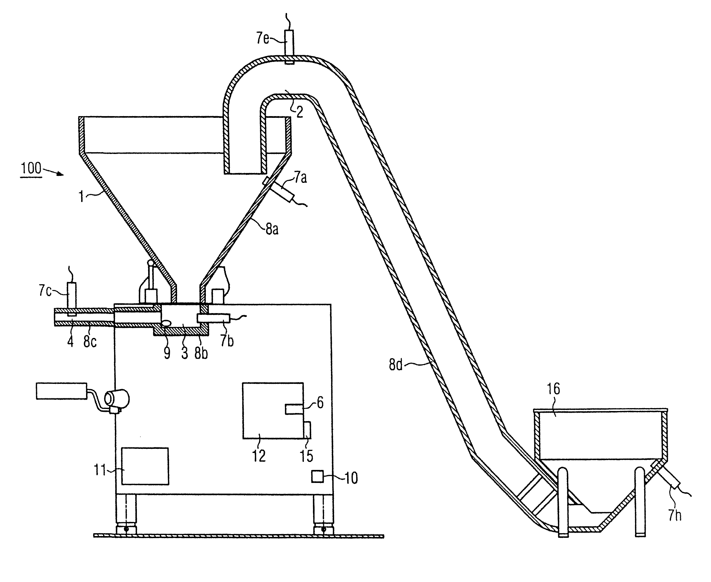
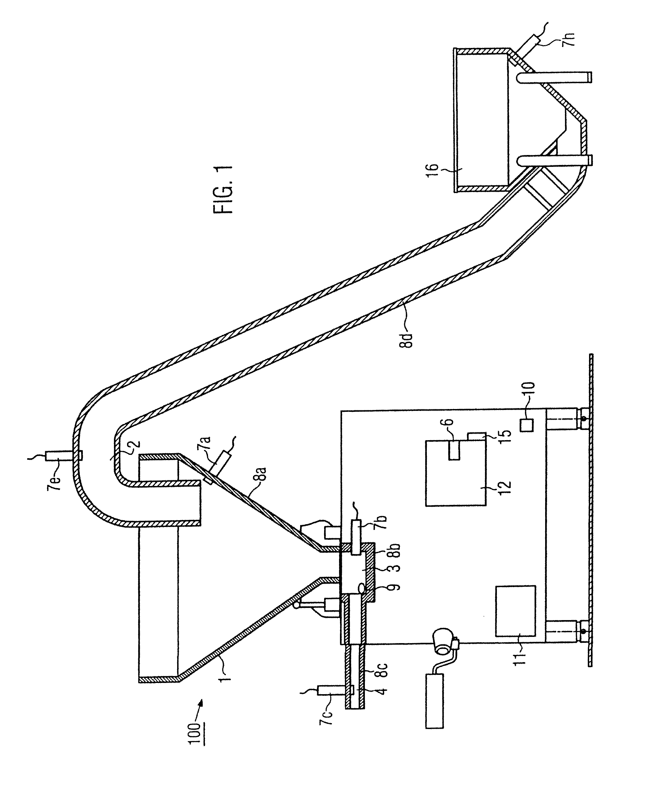
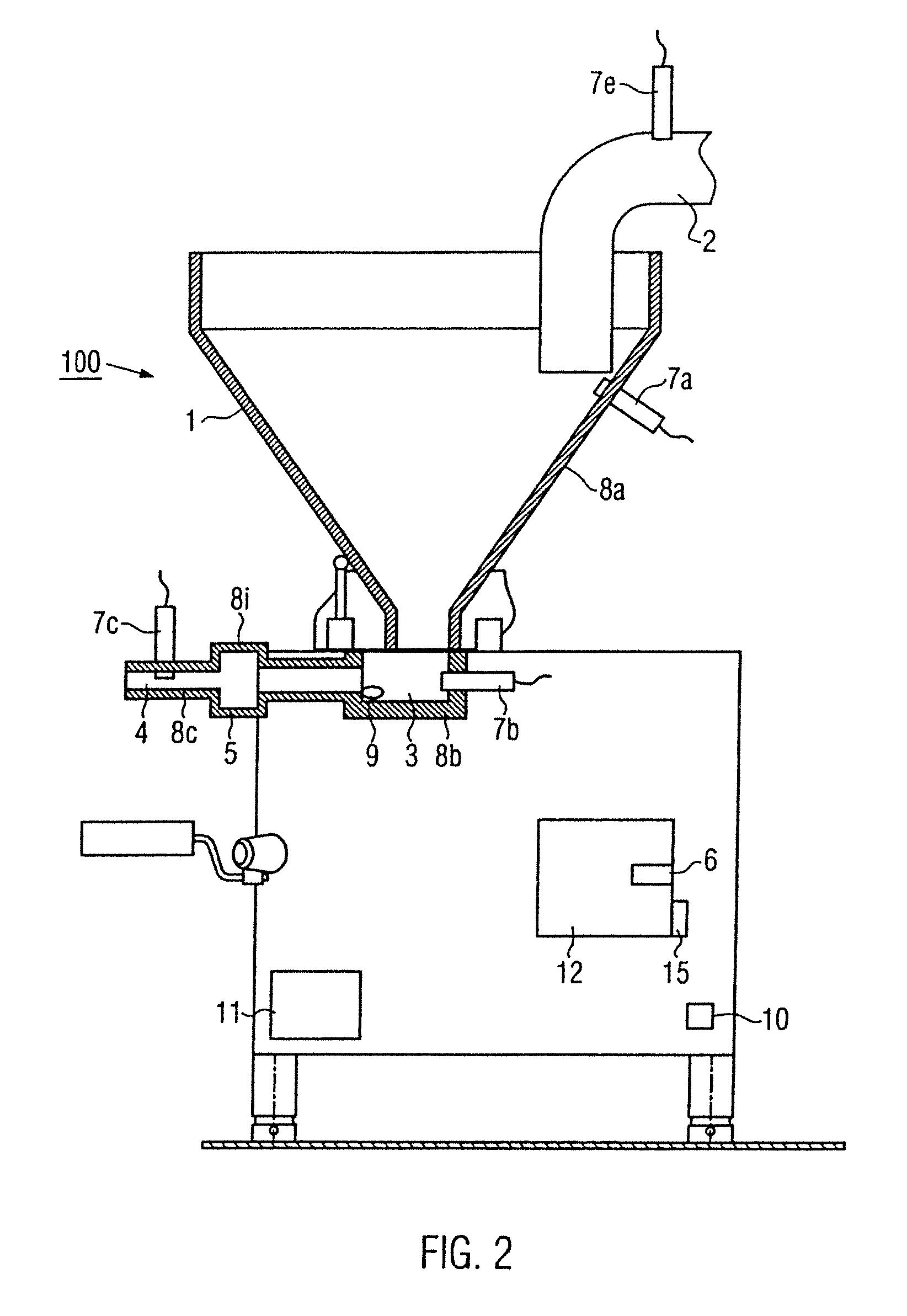
[0024]FIG. 1 illustrates an embodiment of a filling machine 100 according to the disclosure. The filling machine 100 comprises a filling hopper 1, for example a vacuum hopper, in which a negative pressure can be produced. Furthermore, the filling machine 100 comprises a suction pipe 2, through which the paste mass, also designated as filling material in the following, can be passed into the filling hopper 1. The suction pipe 2 is part of a suction intake section for the filling material. A preceding floor-mounted hopper 16 can also be included in the suction intake section. Furthermore, the filling machine also comprises a conveying mechanism 3, which is arranged at the lower end of the conically shaped filling hopper 1. In a familiar manner a conveying mechanism 3 of this type comprises, for example, a vane pump or a screw conveyor, which pushes the filling material out of the filling hopper 1 in the direction of a filling tube 4, wherein the filling material is pushed into a sausa...


PUM


Abstract

A method and a filling machine for the temperature control of a mass flow in a filling machine, wherein the mass flow passes through several sections. In order to also process temperature-sensitive types of filling material reliably with the minimum outlay, the temperature of the filling material is measured in several sections of the filling machine and the temperature of the filling material is controlled by a heating / cooling device to a certain temperature in dependence of the measured temperatures.

Description

CROSS REFERENCE TO RELATED APPLICATION[0001]The present application claims the benefit of priority of European Patent Application No. EP 07010627.3, filed May 29, 2008.The entire text of the priority application is incorporated herein by reference in its entirety.FIELD OF THE DISCLOSURE[0002]The disclosure relates to a method and a filling machine, such as used in sausage-making operations.BACKGROUND[0003]Filling machines of this nature for filling sausage casings with paste material are already known. During the processing of certain types of filling material, e.g. raw sausage, it should be ensured that the temperature of the filling material does not undercut or exceed a certain temperature in the complete processing chain. If the filling material undercuts or exceeds a certain temperature, it cannot then be processed further. For this reason currently the temperature of the mass flow is acquired, wherein on reaching a certain limit the operator must intervene actively and manuall...

Claims


Application Information

Patent Timeline
Patent Type & Authority Patents(United States)
IPC IPC(8): A22C11/00A23L13/00
CPCA22C11/0245
Inventor MAILE, BERNDWILLBURGER, PETER
Owner ALBERT HANDTMANN MASCHFABRICK
Learn More