
Personal upper body support device for lower back muscles assist

a technology of upper body support and lower back muscles, which is applied in the field of therapeutic devices, can solve problems such as remained room for improvement, and achieve the effect of preventing back strain and quick and easy adjustment of its tension

Inactive Publication Date: 2010-06-29
BABCOCK MICHAEL ANTHONY
View PDF35 Cites 55 Cited by
  • Summary
  • Abstract
  • Description
  • Claims
  • Application Information

AI Technical Summary

Benefits of technology

[0036]In addition, springs are incorporated within this differential mechanism that provide a gradient type of compressive resistance that can be altered quickly and easily. Through simply twisting a knob, wearers can dial-in the optimal amount of spring assist and / or the angle at which a bending limit engages. If desired, this spring-loading can be increased to a point where the stomach muscles are required to overcome the springs in order to bend over. In this situation, to return upright the stomach muscles would be relaxed and the springs would push the upper-body back to its upright position.
[0056]Currently the adjustable (telescopic) shaft 56 (FIG. 3) with a padded roller 51 at its upper end for rolling up and down the stomach / chest (as what happens while bending forward) seems to be the most versatile. Two vertical shafts 90 having a horizontal bridging member 92 in the form of webbing, fabric or a flexible plate either attached or stretched between them (as on the back of a beach or director's chair) also works well (FIG. 10).

Problems solved by technology

As most of these previous devices have not become popular, or even heard of, it would appear that there remained room for improvements.

Method used


Image

  • Personal upper body support device for lower back muscles assist
  • Personal upper body support device for lower back muscles assist
  • Personal upper body support device for lower back muscles assist

Examples


Embodiment Construction

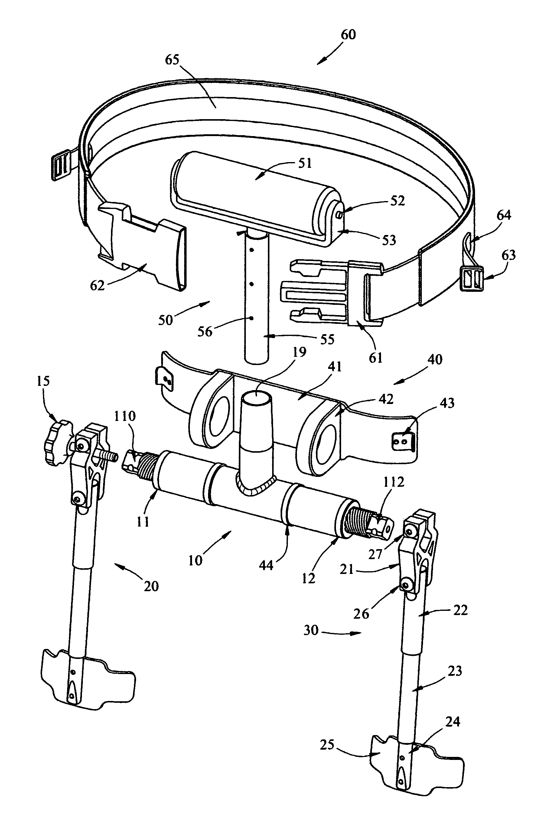
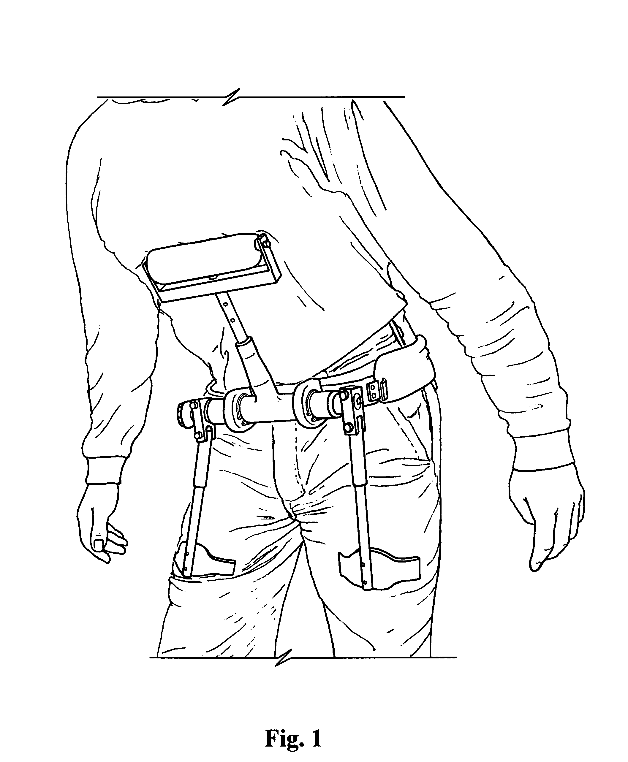
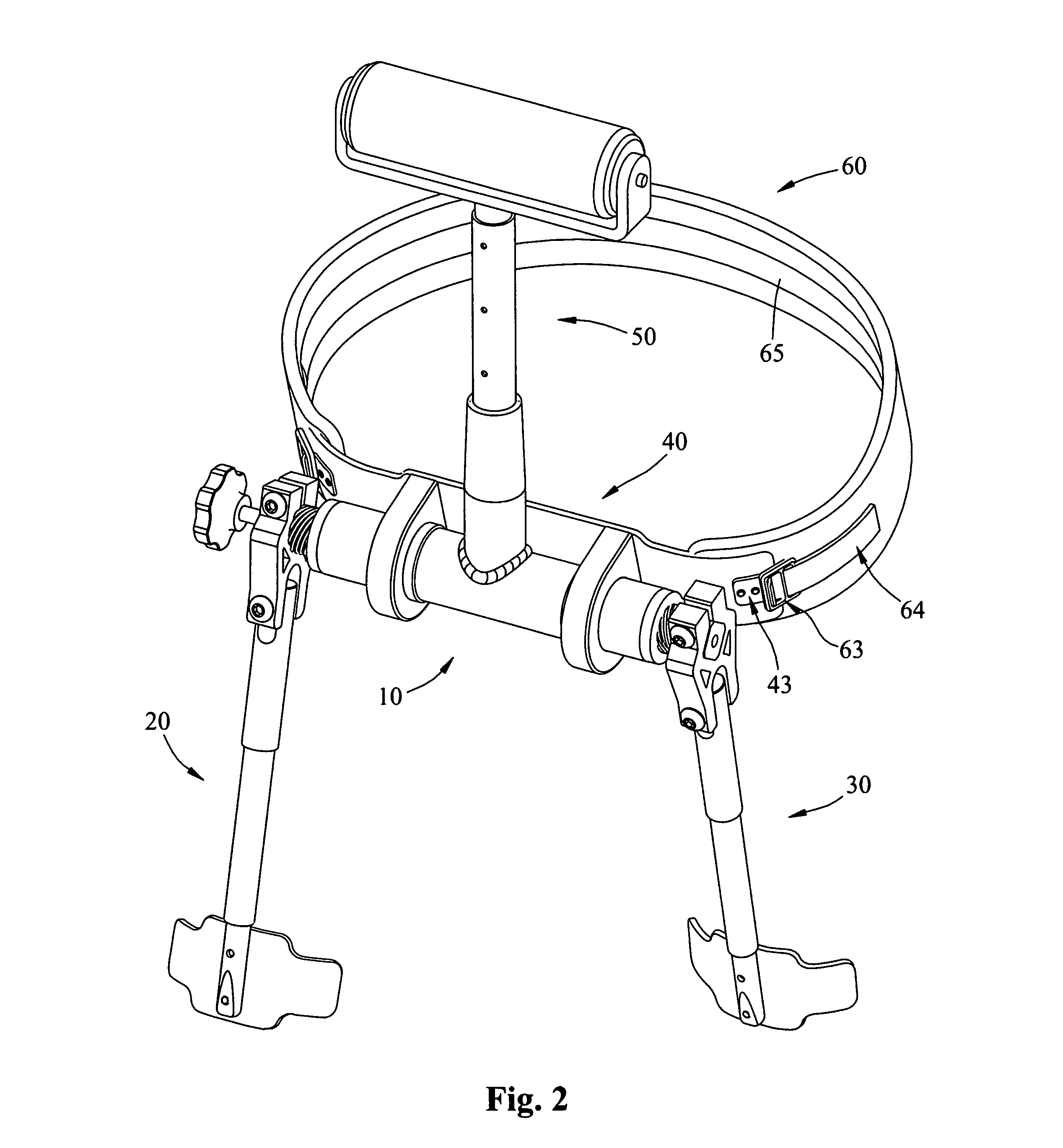
[0068]The overall operating function of my device is to assist, even relieve, the workload of the wearer's lower back muscles. This is accomplished through re-routing the wearer's overhanging upper body weight to the fronts of both upper legs. When breaking down the basic principles involved in accomplishing this, the external make-up of my device could be compared to a teeter-totter type lever, only more elaborate. A teeter-totter uses a central fulcrum; the fulcrum of my device is the saddle means and the belt.

[0069]The belt holds the saddle means, thereby the central horizontal tubular member of the main-body against the front of the wearer's pelvis. As the chest and legs apply opposing forces to the ends of this lever example, the belt pulls from the buttocks to hold the device from being pushed away. When enough force is applied to overcome the spring resistance, the lever bends at its center with a means to vary how much effort is required before it bends.

[0070]My device also ...


PUM


Abstract

A device that straps against the front of one's pelvis and features chest and leg engagements extending from a central main-body to create a personal upper body support system. As wearer bends forward from the waist, the leg engagements leverage oppositely threaded shafts to screw together into an internally threaded main-body either against a powerful spring means used to effect a compressive stop or a spring-back counter force to the wearer's overhanging upper body weight. A knob-ended threaded rod screws through one of the shafts to adjust the point of engagement and / or spring tension. This device creates a prop effect between the wearer's chest and upper legs. The oppositely threaded shafts provide a unique mechanism that divides the transferred load equally to each leg regardless of leg stance, as well as for allowing unrestricted upright walking.

Description

BACKGROUND OF THE INVENTION[0001]My invention relates to orthopedic and therapeutic devices worn to assist the musculoskeletal functions of the human body. More specifically, this device addresses several very common conditions of the lower back that can range anywhere between bothersome to life altering. The most common condition is simply low back muscle strain resulting from overuse. Continued abuse of these muscles often progress into much more serious injuries such as shifted vertebras and herniated discs that impinge on nerves. Nerve impingement is not only painful, but it can result in permanent damage that even surgery cannot fix.[0002]Lower back injuries and degenerative conditions affect millions of people annually. Sadly, many of these statistics could have been prevented. But it is human nature to think it won't happen to us. So we keep abusing our backs until we can no longer tolerate the pain. By then, all too often it is too late for natural recovery; the damage is so...

Claims


Application Information

Patent Timeline
Patent Type & Authority Patents(United States)
IPC IPC(8): A61F5/00
CPCA61F5/026A61F5/028A61H3/008A61H1/0292A61H3/00A61H2201/165A61H2201/1619A61H2201/163A61H2201/164A61H2201/1645A61H2201/0192
Inventor BABCOCK, MICHAEL ANTHONY
Owner BABCOCK MICHAEL ANTHONY
Learn More