Lamp which is closed on two sides

a technology of two sides and closed tubes, applied in the field of lamps which, can solve the problem of relatively high risk of fracturing

Inactive Publication Date: 2010-06-29
OSRAM GMBH
View PDF16 Cites 0 Cited by
  • Summary
  • Abstract
  • Description
  • Claims
  • Application Information

AI Technical Summary

Benefits of technology

[0003]It is an object of the present invention to provide a lamp which is closed on two sides and has an elongate bulb, which is closed off in a vacuum-tight manner, defines a longitudinal axis and is closed at opposite ends by sealing parts, with in each case one cap being fitted at one end, the cap having an electrical contact element which is connected in an electrically conductive manner to a supply conductor leading to a luminous means, the contact element being accommodated in a tubular extension of the sealing part, and which lamp has a simple, securely fitted and precisely oriented cap.
[0007]It is preferable to use three barbs which are distributed uniformly over the circumference of the attachment part. They are therefore arranged at intervals of 120° with respect to one another. This ensures reliable centering with little outlay on material.
[0013]In one particularly preferred embodiment, the cap comprises an adjustment part made from spring sheet. It comprises a base part, which covers one plane and from which two differently configured centering parts project radially in opposite directions. The first centering part is shaped similarly to a W and projects out of the plane of the base part along the latter. The two reversal points in the W are in contact with the extension part of the sealing part, and in particular at least one of the reversal points is even fused into the extension part, and moreover the second centering part connects the contact element to the base part, which imparts additional stability. The base part may comprise two struts which run laterally with respect to the supply conductor and are connected by at least one connecting bridge, also referred to as a yoke. It is preferable for there to be two or even three connecting bridges in different planes. This further improves stability.
[0014]The supply conductor may be in contact with some of the connecting bridges or may be fixedly connected thereto, which promotes the exactness of centering. This aspect is improved still further by virtue of the first centering element having a free end which is forked, so that it can automatically adjust to the supply conductor.

Problems solved by technology

One drawback of this is that the contact elements can easily become tilted, and consequently they are no longer positioned exactly transversely with respect to the lamp axis and, moreover, the risk of fracturing is relatively high.

Method used


Image

  • Lamp which is closed on two sides
  • Lamp which is closed on two sides
  • Lamp which is closed on two sides

Examples


Embodiment Construction

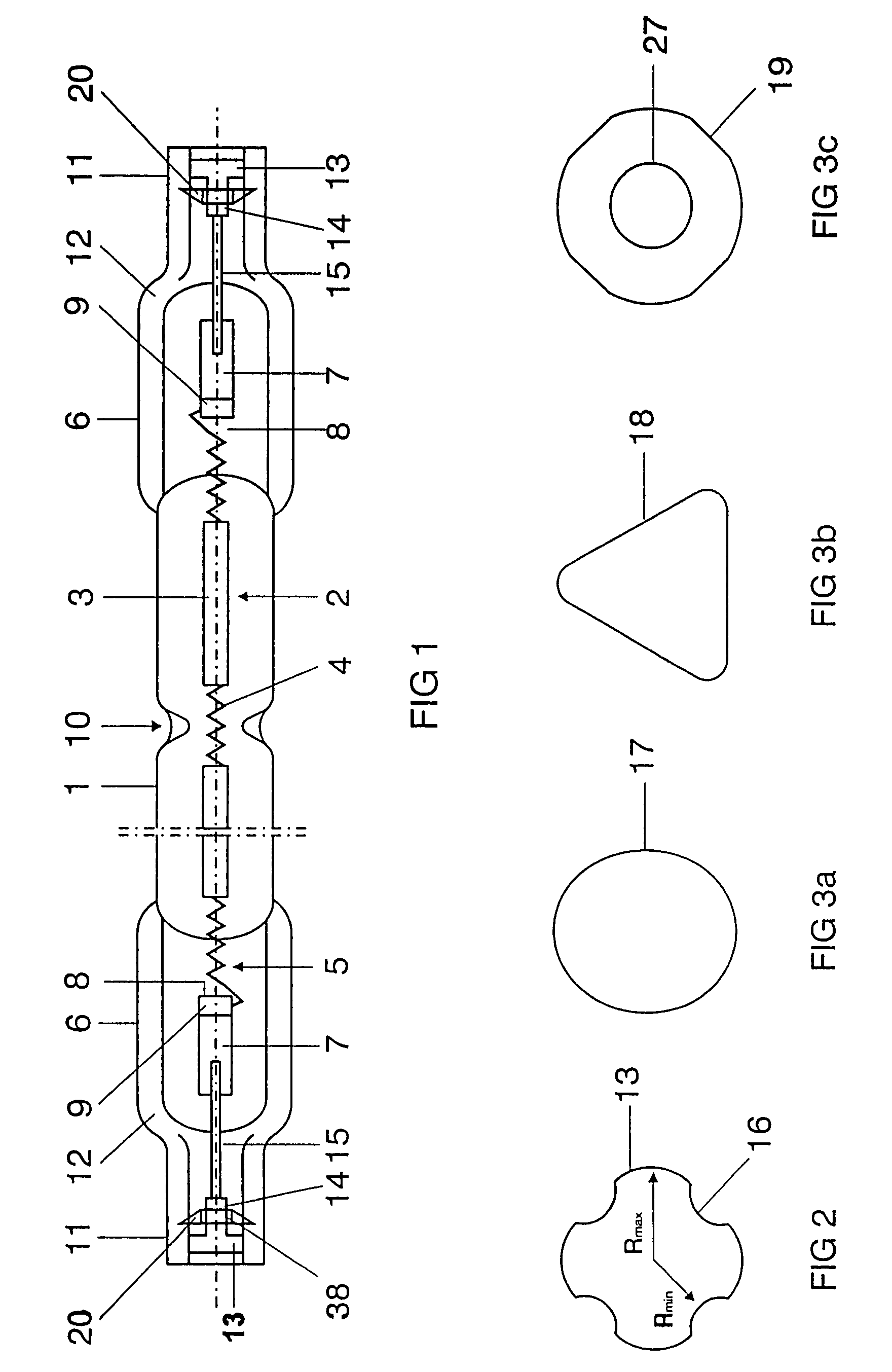
[0026]FIG. 1 shows a side view of an incandescent halogen lamp which is pinched on two sides. It comprises a cylindrical bulb 1 in which a luminous body 2 is arranged axially. The luminous body is held in the bulb 1 by lugs 10.

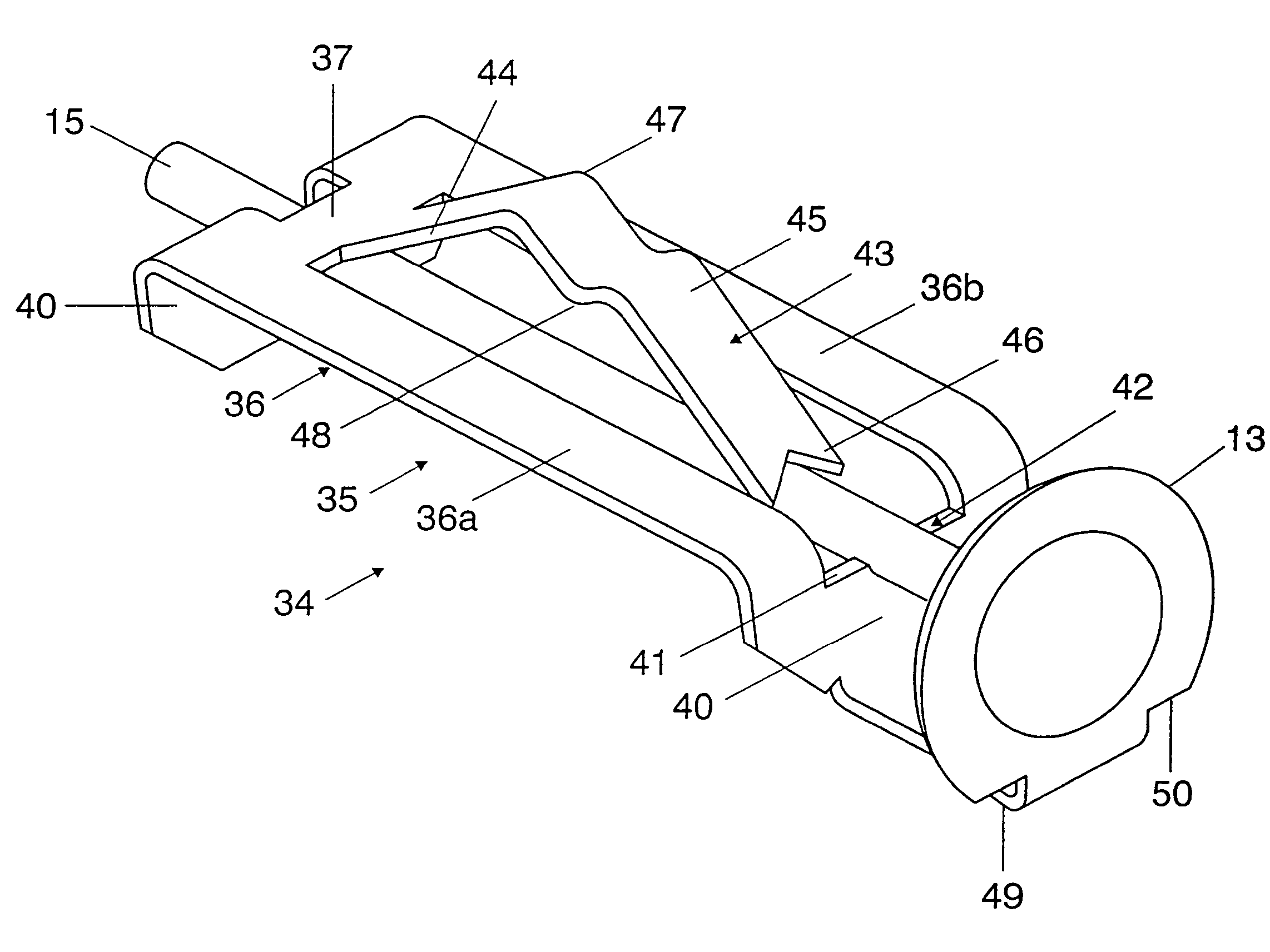
[0027]The luminous body 2 comprises luminous sections 3 with a small pitch which are separated from one another by non-luminous sections 4 with a large pitch. The ends 5 of the luminous body also comprise non-luminous sections with a large pitch. With regard to their function as internal supply conductor, the ends 5 are embedded directly in the pinch 6, where they are connected to a pinch foil 7. That end 8 of the foil 7 which faces the luminous body is bent over within the pinch 6, with the luminous body end 5 being introduced into the bend 9, thereby producing an electrical contact with the foil 7 by purely mechanical means.

[0028]A tubular glass sleeve 11 with an external diameter of 7 mm and an internal diameter of 5 mm is formed integrally on the outside o...


PUM


Abstract

The elongate bulb (1) of the lamp, which defines a longitudinal axis (A), is closed at opposite ends by sealing parts (6; 32), with in each case one cap being fitted at one end, the cap having an electrical contact element (13; 25) which is connected in an electrically conductive manner to a supply conductor (15; 21) leading to a luminous means, the contact element being accommodated in a tubular extension (11; 22) of the sealing part; the contact element (13; 25) has an attachment part (14; 24) which is directed inward toward the lamp interior and is equipped with at least two barbs (20; 26) which are in contact with the tubular extension (11; 21).

Description

TECHNICAL FIELD[0001]This application is a divisional of U.S. patent application Ser. No. 10 / 855,623 filed on May 28, 2004, now U.S. Pat. No. 7,253,562 which issued Aug. 7, 2007, which claimed the benefit of the filing date of German patent application 10325553.2, filed on Jun. 5, 2003, the disclosures of which are incorporated herein by reference. The invention relates to a lamp which is closed on two sides and has an elongate bulb, which is closed off in a vacuum-tight manner, defines a longitudinal axis and is closed at opposite ends by sealing parts, with in each case one cap being fitted at one end, the cap having an electrical contact element which is connected in an electrically conductive manner to a supply conductor leading to a luminous means, the contact element being accommodated in a tubular extension of the sealing part. It deals in particular with metal halide lamps.BACKGROUND ART[0002]U.S. Pat. No. 5,932,955 has already disclosed a lamp which is closed on two sides a...

Claims


Application Information

Patent Timeline
Patent Type & Authority Patents(United States)
IPC IPC(8): H01J17/18H01K1/46H01J5/48H01J5/50H01J5/52H01J5/54H01J61/34H01J61/36H01K1/24H01K1/36H01K1/42H01K1/44
CPCH01J5/50H01J5/52H01K1/42H01J61/34H01J61/368H01J5/54H01K1/36
Inventor GRAF, JURGENHOHLFELD, ANDREASHULSEMANN, MICHAELSCHOGL, ANTONTWESTEN, KAREN
Owner OSRAM GMBH
Why Eureka
Try Eureka