Digitally controlled delay-locked loops

a digital delay and loop technology, applied in the field of electronic circuits, can solve the problems of digital delay-locked loops generating a significant phase error between the feedback clock signal and the input reference clock signal, and digital delay-locked loops generating an undesirable amount of jitter in the feedback clock signal

Active Publication Date: 2010-06-29
ALTERA CORP
View PDF20 Cites 19 Cited by
  • Summary
  • Abstract
  • Description
  • Claims
  • Application Information

AI Technical Summary

Benefits of technology

[0004]The present invention includes methods and systems for digitally controlled delay-locked loops. According to some embodiments of the present invention, the digitally controlled delay-locked loops have a phase detector, contro

Problems solved by technology

Many digital delay-locked loops generate a significant phase error between the feedback clock signal and the input reference c

Method used


Image

  • Digitally controlled delay-locked loops
  • Digitally controlled delay-locked loops
  • Digitally controlled delay-locked loops

Examples


Embodiment Construction

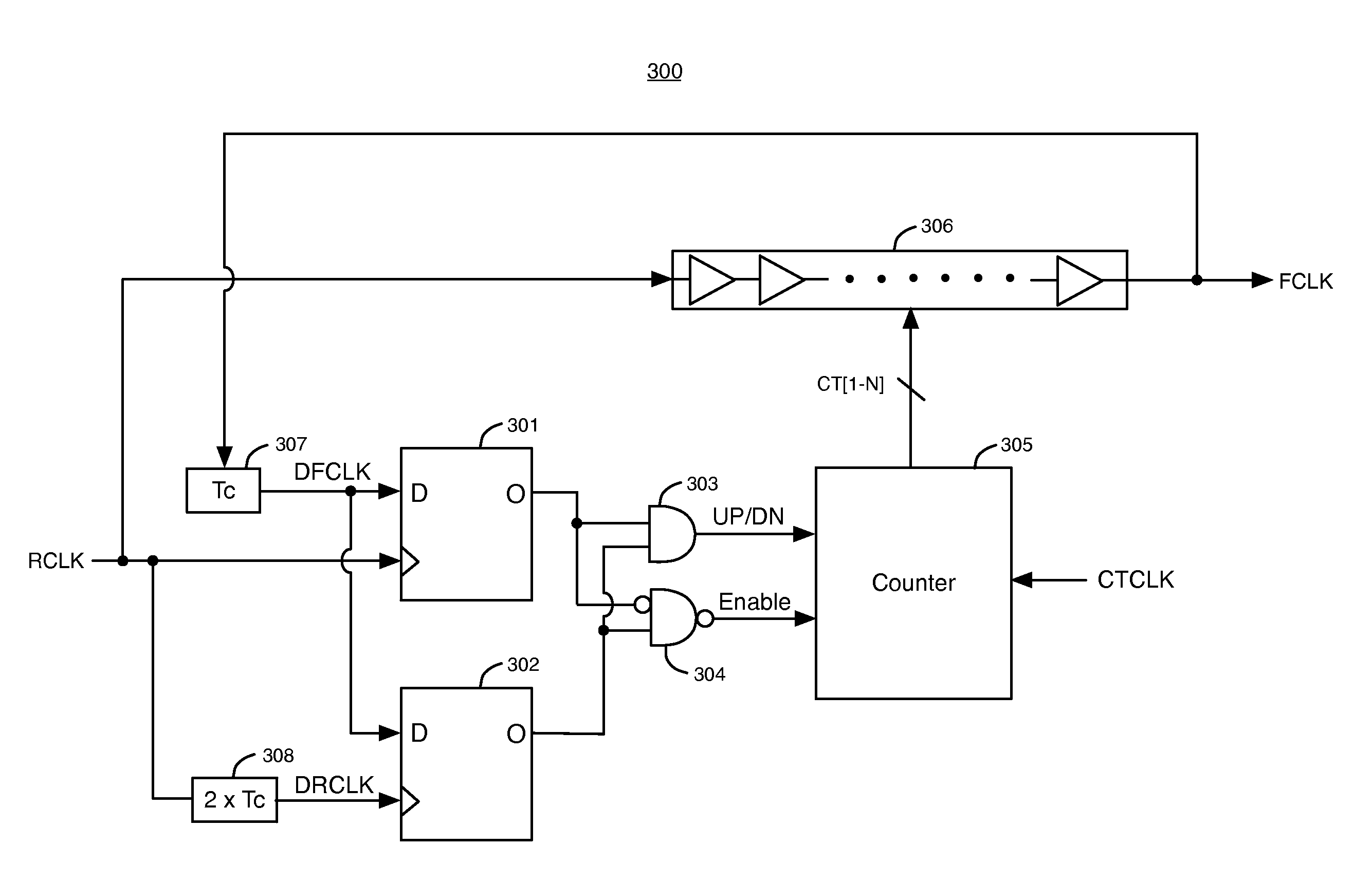
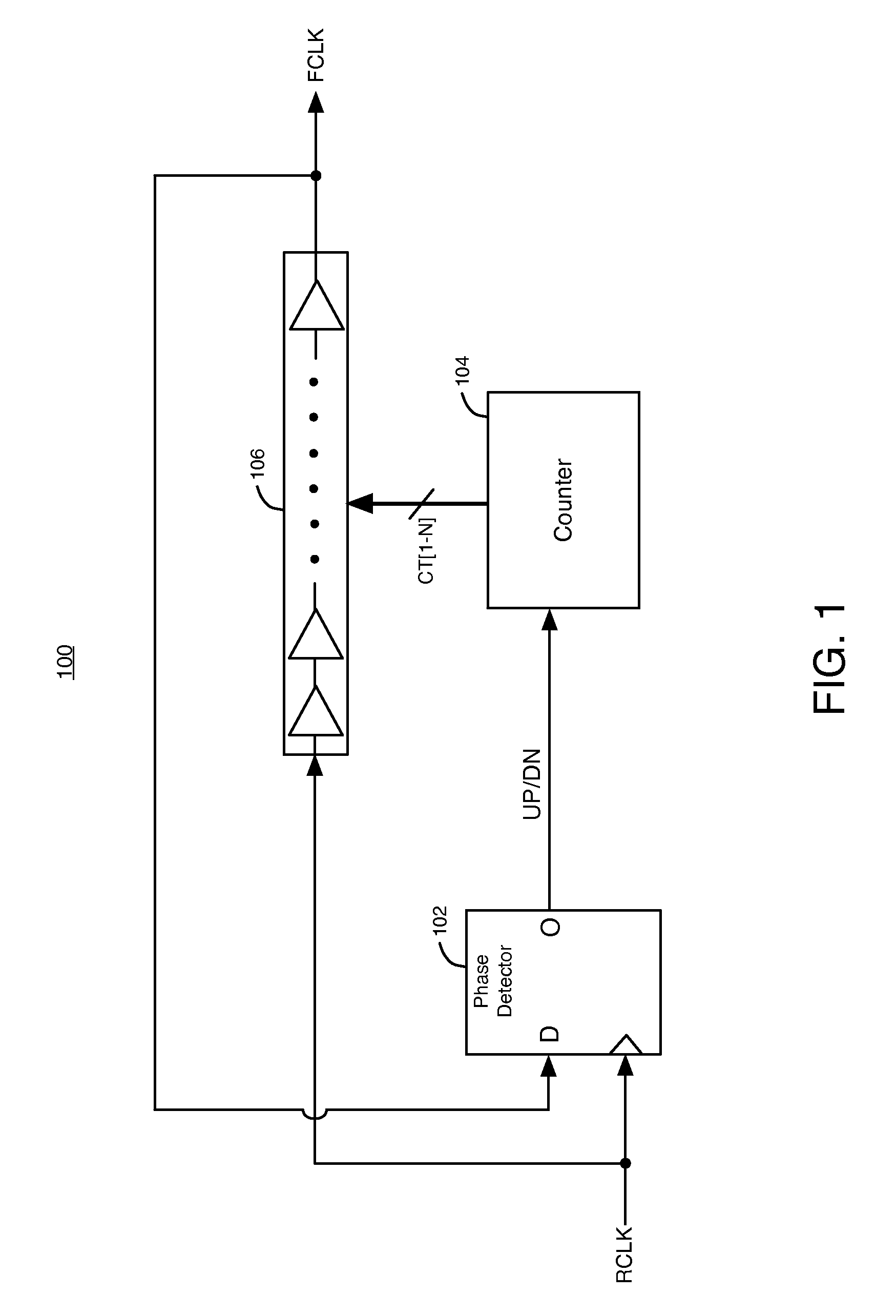
[0017]FIG. 1 illustrates an embodiment of a digital delay-locked loop (DLL) circuit 100. DLL 100 includes phase detector 102, counter 104, and delay chain 106. Delay chain 106 receives a periodic reference clock signal (RCLK) at an input. Delay chain 106 delays RCLK to generate a periodic feedback clock signal (FCLK) at an output.

[0018]Phase detector 102 receives the reference clock signal RCLK at a clock input. The feedback clock signal FCLK from delay chain 106 is fed back to a D input of phase detector 102. Phase detector 102 compares the phases of the reference clock signal RCLK and the feedback clock signal FCLK to generate a digital UP / DN signal.

[0019]The UP / DN signal is transmitted to an input of counter circuit 104. Counter 104 generates a set of digital count signals CT[1-N] that are transmitted to delay chain 106. When the phase of FCLK is ahead of the phase of RCLK, phase detector 102 generates a logic high on the UP / DN signal to slow down the phase of the FCLK signal. Wh...


PUM


Abstract

Digitally controlled delay-locked loops can have a phase detector, control logic, and a delay chain. The control logic generates digital signals in response to an output signal of the phase detector. The delay chain generates a delay that varies in response to the digital signals. In some embodiments, the control logic maintains logic states of the digital signals constant in response to an enable signal to maintain the delay of the delay chain constant in a lock mode of the digitally controlled delay-locked loop. In other embodiments, the delay of the delay chain varies by a discrete time period in response to a change in logic states of the digital signals, and the maximum phase error between a phase of the reference clock signal and a phase of the feedback clock signal is less than the discrete time period when the digitally controlled delay-locked loop is in a lock mode.

Description

BACKGROUND OF THE INVENTION[0001]The present invention relates to electronic circuits, and more particularly, to digitally controlled delay-locked loop circuits.[0002]Digital delay-locked loop circuits typically maintain a phase relationship between an input reference clock signal and a feedback clock signal. Many digital delay-locked loops generate a significant phase error between the feedback clock signal and the input reference clock signal. In addition, many digital delay locked loops generate an undesirable amount of jitter in the feedback clock signal.[0003]Therefore, it would be desirable to provide a digital delay-lock loop that can generate a clock signal having reduced jitter and a reduced phase error relative to an input reference clock signal.BRIEF SUMMARY OF THE INVENTION[0004]The present invention includes methods and systems for digitally controlled delay-locked loops. According to some embodiments of the present invention, the digitally controlled delay-locked loops...

Claims


Application Information

Patent Timeline
IPC IPC(8): H03L7/06
CPCG11C7/22H03L7/091H03L7/0814G11C7/222H03L7/0816
Inventor LU, SEAN SHAU-TUSUNG, CHIAKANGHUANG, JOSEPHCHONG, YAN
Owner ALTERA CORP
Why Eureka
Try Eureka