Illumination optical system that uses a solid-state lighting element which generates white light, and an optical device equipped therewith

an optical system and light source technology, applied in the field of illumination optical systems, can solve the problems of increased burden on individuals who perform diagnoses, inconvenient operation, and erroneous diagnosis, and achieve the effects of reducing the cost of operation, and reducing the number of optical devices

Active Publication Date: 2010-06-29
EVIDENT CORP
View PDF5 Cites 30 Cited by
  • Summary
  • Abstract
  • Description
  • Claims
  • Application Information

AI Technical Summary

Problems solved by technology

During such examinations, if the spectral distribution of the illumination light source is changed, even when observing the same specimen using a microscope, the color of the observation object that may be observed either visually, or through a solid-state imaging element such as a CCD or the like, may result in erroneous diagnostic results.
Owing to this, an illumination optical system that is equipped with a solid-state lighting element to generate white light (such as disclosed in JP 2002-543453 and in Japanese Laid Open Patent Application 2005-148296) cannot be used in its existent state for the diagnosis of pathological segmentations, and the like, using a microscope that is equipped with a halogen light source, since the diagnostic standards required when using illumination of an observation body with a microscope that employs a halogen light source are different than when using illumination of an observation body with a microscope that employs a solid-state lighting element.
Thus, an increased burden would be placed on individuals who perform diagnoses, owing to the concern about the possibility of an error in the diagnosis occurring due to an inapplicable diagnostic standard being applied for a given light source type.
In industrial applications as well, when mixing an examination performed using a microscope having a conventional halogen light source with an examination performed using a microscope having a white light LED (for example, in the case of using color to detect defect(s) of a magnetic head formed from multiple layers), there are inconveniences that are similar to those found in biological and medical applications.

Method used


Image

  • Illumination optical system that uses a solid-state lighting element which generates white light, and an optical device equipped therewith
  • Illumination optical system that uses a solid-state lighting element which generates white light, and an optical device equipped therewith
  • Illumination optical system that uses a solid-state lighting element which generates white light, and an optical device equipped therewith

Examples


example 1

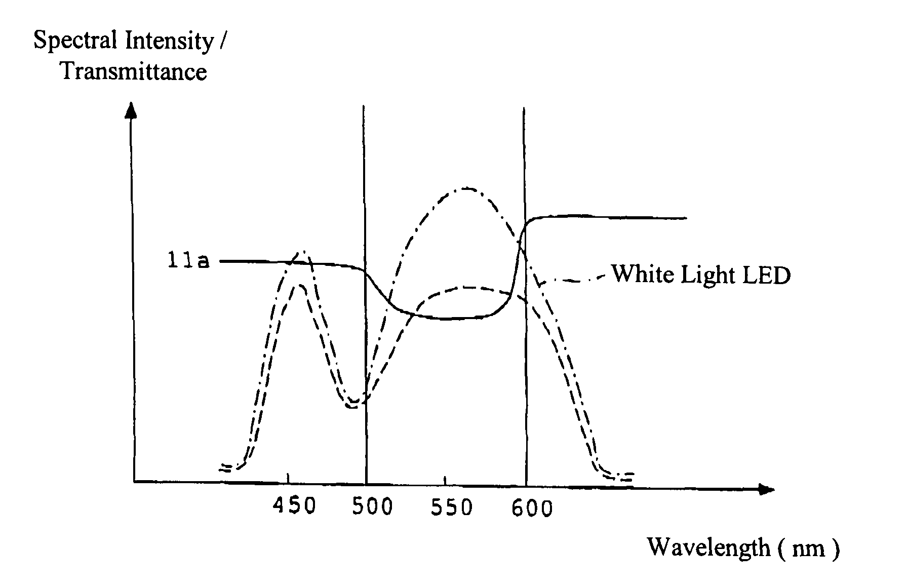
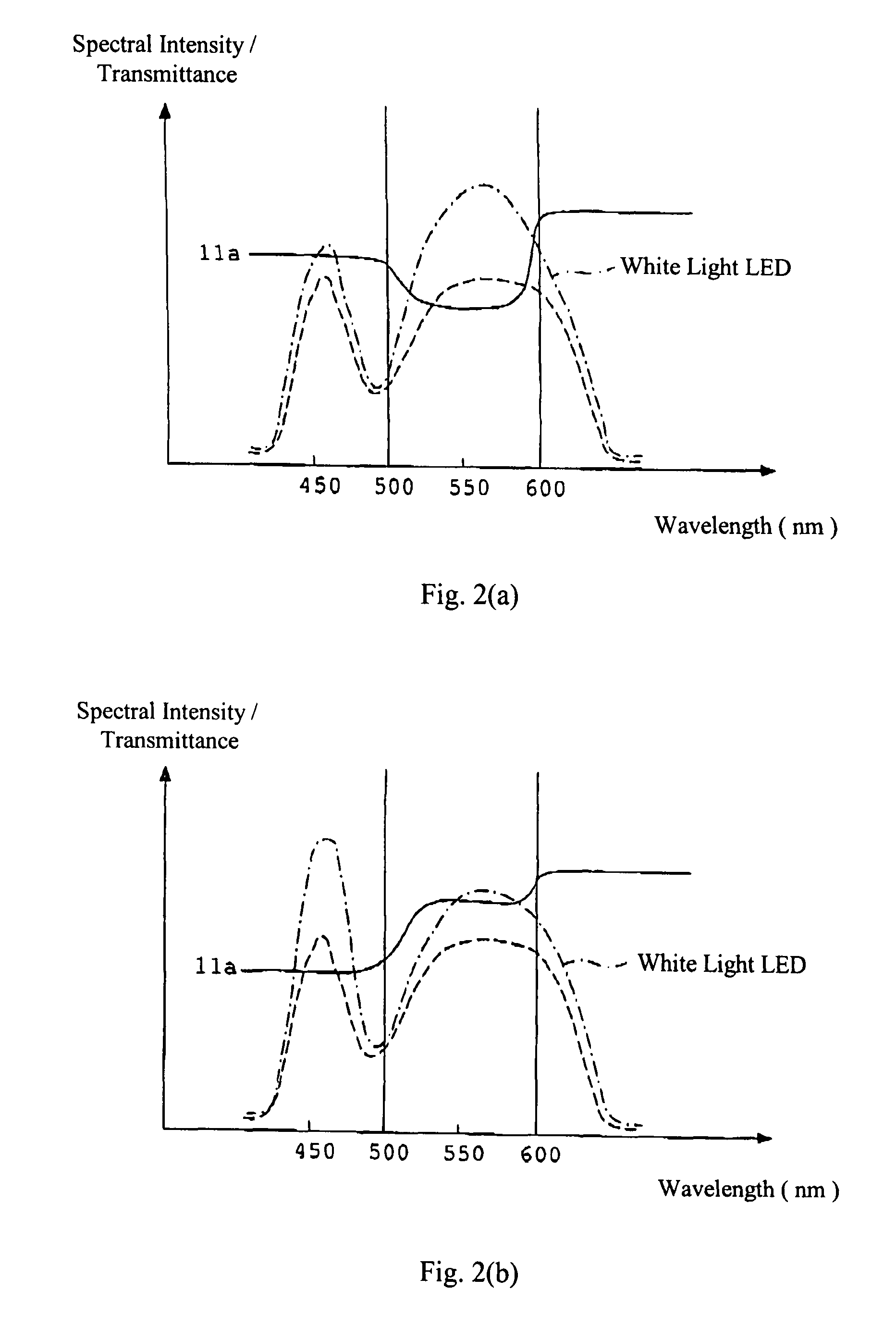
[0041]FIG. 2(a) shows the spectral intensity (i.e., light intensity as a function of wavelength) that is emitted by a first example of a white light LED (dot-dash line) that may be used in the illumination optical system shown in FIG. 1, the spectral transmittance of a first example of a wavelength distribution conversion element 11a (solid line) that may be used in the illumination optical system shown in FIG. 1, and the spectral intensity when the white light LED and the wavelength distribution conversion element 11a having the characteristics shown in FIG. 2(a) are used in combination (dash line) according to a first example of illumination optical system according to the present invention.

[0042]The wavelength distribution conversion element has a spectral transmittance profile that includes specified wavelength regions within which the transmittance is nearly constant with increasing wavelength so as to form a step of nearly even intensity, and has specified wavelength regions w...

example 2

[0044]FIG. 2(b) shows the spectral intensity that is emitted by a second example of a white light LED (dot-dash line) that may be used in the illumination optical system shown in FIG. 1, the spectral transmittance of a second example of a wavelength distribution conversion element 11a (solid line) that may be used in the illumination optical system shown in FIG. 1, and the spectral intensity of light output when the white light LED and the wavelength distribution conversion element 11a having the characteristics shown in FIG. 2(b) are used in combination (dash line) according to a second example of illumination optical system according to the present invention.

[0045]As shown in FIG. 2(b), the wavelength distribution conversion element 11a has a transmittance, within a specified wavelength region having wavelengths longer than approximately 500 nm and shorter than approximately 600 nm, that is higher than the transmittance of the wavelength distribution conversion element within a sp...

example 3

[0046]FIG. 3(a) shows the spectral intensity that is emitted by a third example of a white light LED (dot-dash line) that may be used in the illumination optical system shown in FIG. 1, the spectral transmittances of a first filter 11b1 and a second filter 11b2 that, in tandem, comprise a third example of a wavelength distribution conversion element in the illumination optical system shown in FIG. 1, and the spectral intensity of light output when the white light LED and the wavelength distribution conversion element having the characteristics shown in FIG. 3(a) are used in combination (dash line) according to a third example of illumination optical system according to the present invention. In this example as well as the next example, the wavelength distribution conversion element is formed of multiple filters that are positioned in tandem, one for each peak intensity emitted by the white light LED. As shown in FIG. 3(a) for this example, the wavelength distribution conversion elem...


PUM


Abstract

An illumination optical system for use in a microscope or electronic endoscope includes a solid-state lighting element that generates light having a spectral profile with peak intensities at multiple wavelengths such that the light output by said solid-state lighting element is perceived by an observer as being white in color, and a wavelength distribution conversion element having a spectral transmittance profile that includes specified wavelength regions within which the transmittance is nearly constant with increasing wavelength so as to form a step of nearly even intensity, and having specified wavelength regions within which the transmittance changes with increasing wavelength so as to form a transition region. By the combined effect of the solid-state lighting element and the wavelength distribution conversion element, the wavelength distribution of the light generated by the illumination optical system more closely resembles the wavelength distribution of daylight than the light generated by the solid-state lighting element.

Description

[0001]The present application claims the benefit of foreign priority under 35 U.S.C. §119 of JP 2006-137776, filed May 17, 2006, the contents of which are hereby incorporated by reference.BACKGROUND OF THE INVENTION[0002]Conventionally, an ordinary microscope (meaning one that does not provide stereo viewing optics so that a 3-D image is viewable) as shown in FIG. 8 may be formed of a lamp housing 1 having a light source 2 that generates illumination light; a collector lens 3 that converts light from the light source 2 into a substantially collimated light; a light-balanced daylight filter 9 that causes the spectral content of the light emitted by the light source to more closely resemble that of daylight; a diaphragm 4 that functions as a field stop to restrict the illumination light; a field lens 5 that converts the substantially collimated light emitted from the lamp housing 1 to a collected light flux; an aperture diaphragm 6; and a condenser lens 7 through which the illuminatio...

Claims


Application Information

Patent Timeline
Patent Type & Authority Patents(United States)
IPC IPC(8): G02B27/14G02B5/28G03B21/14
CPCG02B23/2461G02B21/06
Inventor YAMAZAKI, KENTARO
Owner EVIDENT CORP
Why Eureka
Try Eureka