
Generating static performance modeling factors in a deployed system

Active Publication Date: 2010-06-29
MICROSOFT TECH LICENSING LLC
View PDF2 Cites 7 Cited by
  • Summary
  • Abstract
  • Description
  • Claims
  • Application Information

AI Technical Summary

Problems solved by technology

Each of the components is susceptible to event tracing while executing on the computing system.

Method used


Image

  • Generating static performance modeling factors in a deployed system
  • Generating static performance modeling factors in a deployed system
  • Generating static performance modeling factors in a deployed system

Examples


Embodiment Construction

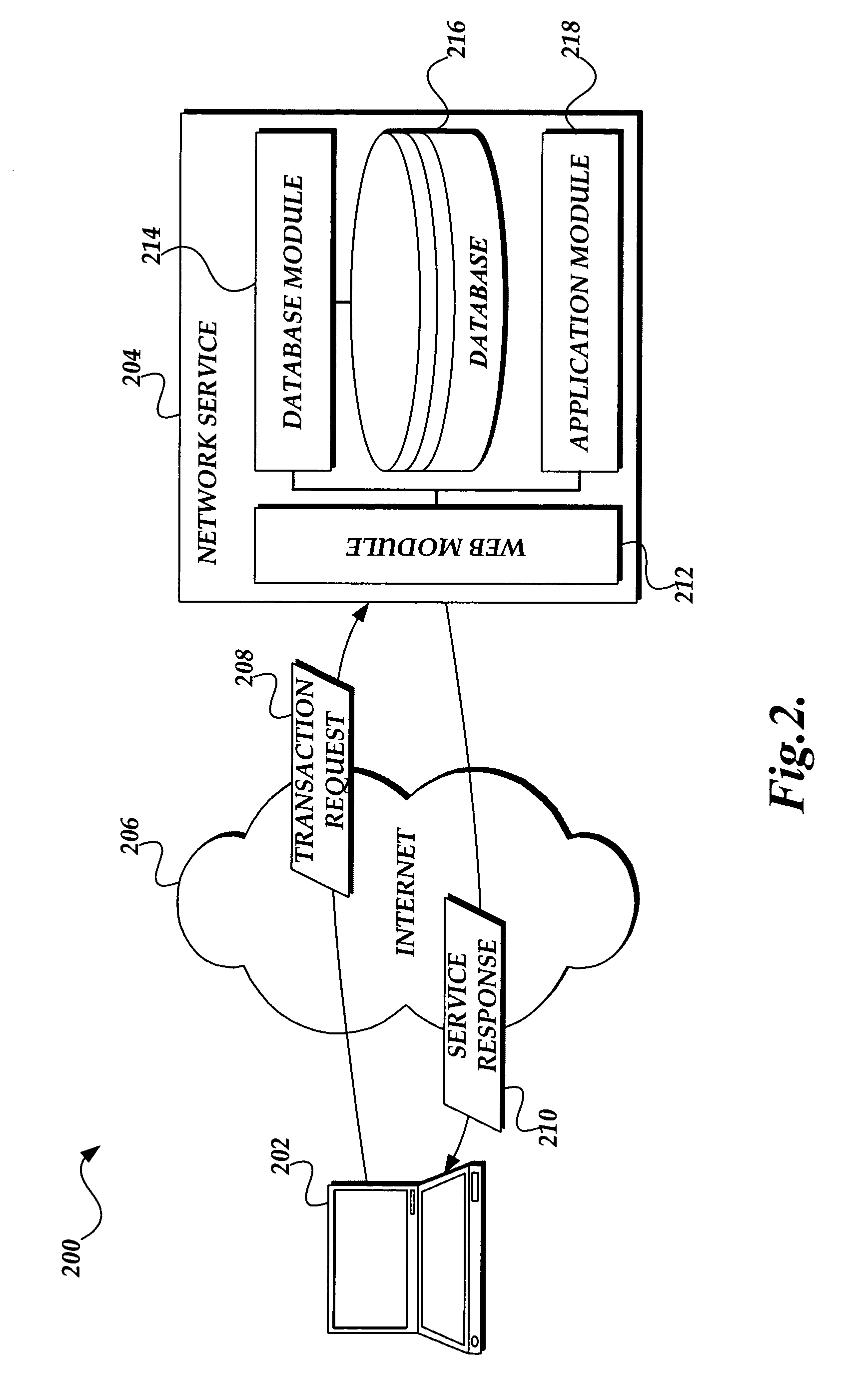
[0019]According to aspects of the present invention, static performance factors 114 can now be derived in a “live”, deployed subject system. FIG. 2 is a pictorial diagram illustrating an exemplary operating environment 200 suitable for implementing aspects of the present invention, i.e., deriving static performance factors 114 in a “live”, deployed subject system. In particular, FIG. 2 illustrates an exemplary single-machine network service 204 (the network service 204 being the subject system to be modeled) communicating with a client computer 202 over the Internet 206, where the network service / subject system provides a to-be-modeled service to the client computer.

[0020]As those skilled in the art will appreciate, typical of this type of system, the client computer 202 submits transaction requests, such as transaction request 208 to the network service 204. In turn, the network service 204 processes the received transaction request 208, and in many cases returns a service response...


PUM


Abstract

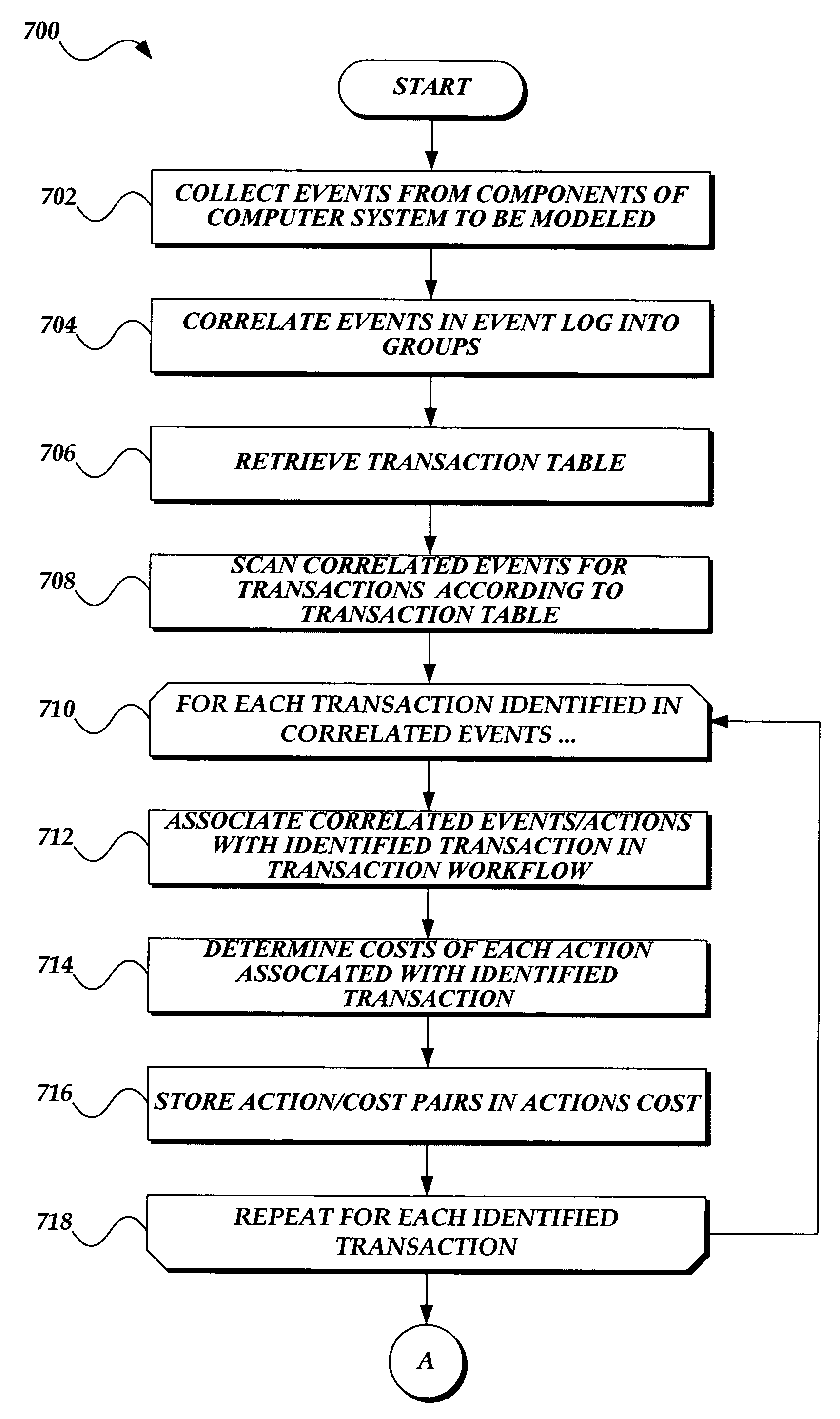
A computing system for determining performance factors for using in performance modeling of a deployed subject system, is presented. The computing system includes a plurality of software components comprising the subject system. Each of the components is susceptible to event tracing while executing on the computing system. The computing system includes a tracing component. The tracing component is configured to trace events of the components of the subject system as they execute. The computing system includes a transaction identification table. The transaction identification table comprises starting and ending actions for transactions performed by the subject system. The computing system also includes a transaction identification component that identifies actions from traced events, identifies related actions corresponding to a transaction according to the starting and ending actions in the transaction identification table, and stores the related actions in the transaction workflow data store.

Description

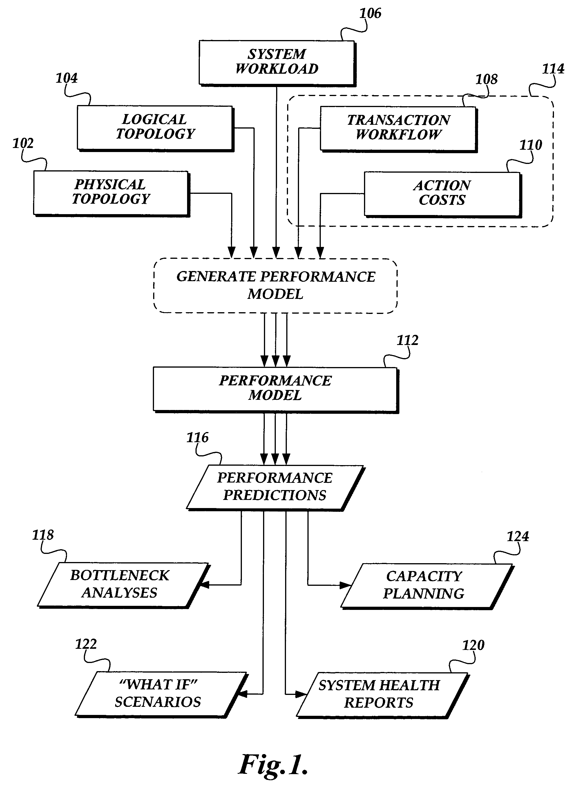
BACKGROUND[0001]As more and more businesses and organizations move toward networked-based services, performance modeling will become increasingly more important. Performance modeling refers to creating a computer model that emulates the performance of a computer system.[0002]As those skilled in the art will appreciate, performance modeling can be used to predict and analyze the effect of various factors on the modeled system, these factors including changes to the input load, or to the configuration of hardware and / or software. Indeed, performance modeling has many benefits including performance debugging (identifying which, if any, system components are performing at unacceptable levels, and why they are underperforming), capacity planning (applying projected loads to the model to analyze what hardware or configurations would be needed to support the projected load), prospective analysis (the ability to test “what if” scenarios with respect to the system, its configuration, and its...

Claims


Application Information

Patent Timeline
Patent Type & Authority Patents(United States)
IPC IPC(8): G06F9/44G06F9/45
CPCG06Q10/10
Inventor LAVIGNE, GLENN FPAPAEFSTATHIOU, EFSTATHIOSHARDWICK, JONATHAN CZHENG, QUANZHANISAACS, REBECCABARHAM, PAUL
Owner MICROSOFT TECH LICENSING LLC
Learn More