Pneumatic biasing of a linear actuator and implementations thereof

a linear actuator and pneumatic technology, applied in the field of linear actuators, can solve the problems of hydraulic actuators that hydraulic actuators that require considerable maintenance, and are often rather large in physical size, so as to improve the operation and reliability of mechanical linear actuators, reduce operating loads, and reduce backlash. the effect of mechanical actuators

Inactive Publication Date: 2010-07-06
UNICO LLC
View PDF26 Cites 16 Cited by
  • Summary
  • Abstract
  • Description
  • Claims
  • Application Information

AI Technical Summary

Benefits of technology

[0011]Practice of the invention thereby precludes, reversal in the direction of forces at the juncture of the driving and driven member of the linear actuator as the linear actuator exerts a bi-directional force along the axis of motion between a first structure and a second structure. By virtue of this arrangement, backlash within the mechanical actuator can be substantially eliminated, with an attendant significant improvement in operation and reliability of the mechanical linear actuator.
[0012]In some forms of the invention, the pneumatic biasing arrangement is also configured to support substantially all of an operating load acting on the actuator, thereby substantially reducing operating loads imposed on the driving and driven members and also substantially reducing the level of operating force which must be exerted by the driving and driven members during operation of the mechanical linear actuator. The pneumatic biasing arrangement may further be configured, in some forms of the invention, to preferentially aid movement of the driven member in one direction, to thereby further reduce the level of operating force which must be exerted by the driving and driven members during movement of driving member in the preferred direction.
[0013]In some forms of a pneumatically biasable mechanical linear actuator, according to the invention, the driving and driven members, and the first and second cylinder elements are all coaxially disposed along the axis of motion, to thereby promote efficient and effective transfer of loads and forces within and applied by the actuator, and also to thereby provide a robust actuator of compact physical size and elegantly simple construction and operation. Such an actuator offers significant advantages over prior actuators including, but not limited to: improved operational performance, efficiency and effectiveness; enhanced reliability and life; reduced need for peripheral support equipment; modular installation and replacement; and the capability to fit multiple actuators into smaller spaces.
[0020]In some forms of the invention, the pneumatic biasing arrangement, of a pneumatically biasable mechanical linear actuator, according to the invention, may be operated without applying a biasing force between the driving and driven members of the mechanical drive arrangement. The pneumatic biasing arrangement may be configured and operated to apply an offset force, for supporting some portion, or substantially all of an operating load acting on the actuator, substantially without applying a biasing force between the driving and driven members of a pneumatically biasable mechanical linear actuator, according to the invention, to thereby at least partially reduce operating loads imposed on the driving and driven members and also at least partially reduce the level of operating force which must be exerted by the driving and driven members during operation of the mechanical linear actuator.

Problems solved by technology

Hydraulic and / or pneumatic actuators are sometimes rather large in physical size, however, and require auxiliary equipment, such as pumps, valves, fluid tanks, and fluid cooling devices, which also are rather large in physical size.
Hydraulic actuators often require considerable maintenance, and are prone to leakage over the operational life of the machine.
Pneumatic actuators typically are incapable of being controlled, to the degree required for modern die press operations.
Despite their significant inherent advantages, in a number of respects, over hydraulic actuators, the use of mechanical actuators in material forming machinery has been limited to date, due to wear and fatigue failure of the mechanical components of the mechanical actuator resulting from the large forces and cyclical loading on the mechanical components, inherent with the use of linear actuators in material forming machinery.

Method used


Image

  • Pneumatic biasing of a linear actuator and implementations thereof
  • Pneumatic biasing of a linear actuator and implementations thereof
  • Pneumatic biasing of a linear actuator and implementations thereof

Examples


exemplary embodiment 100

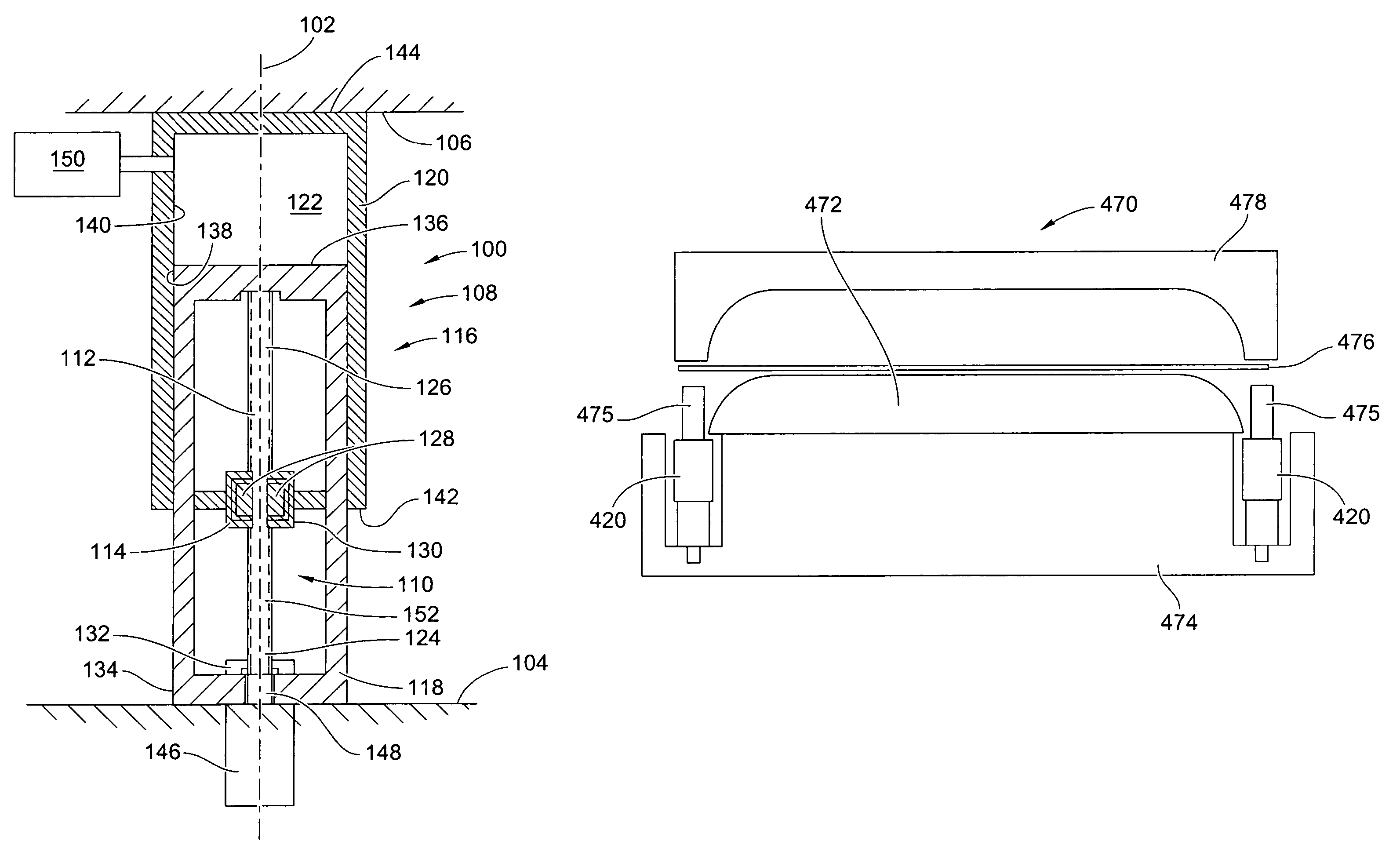
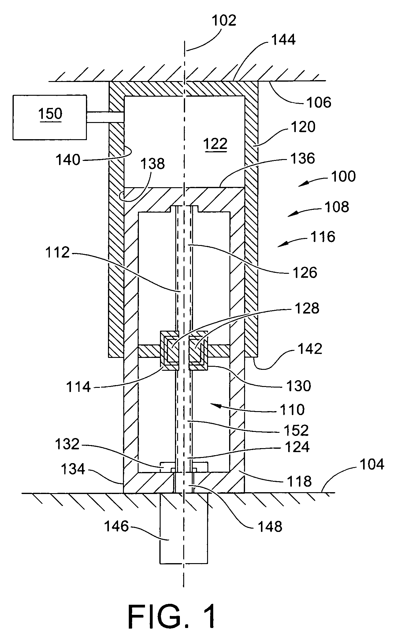
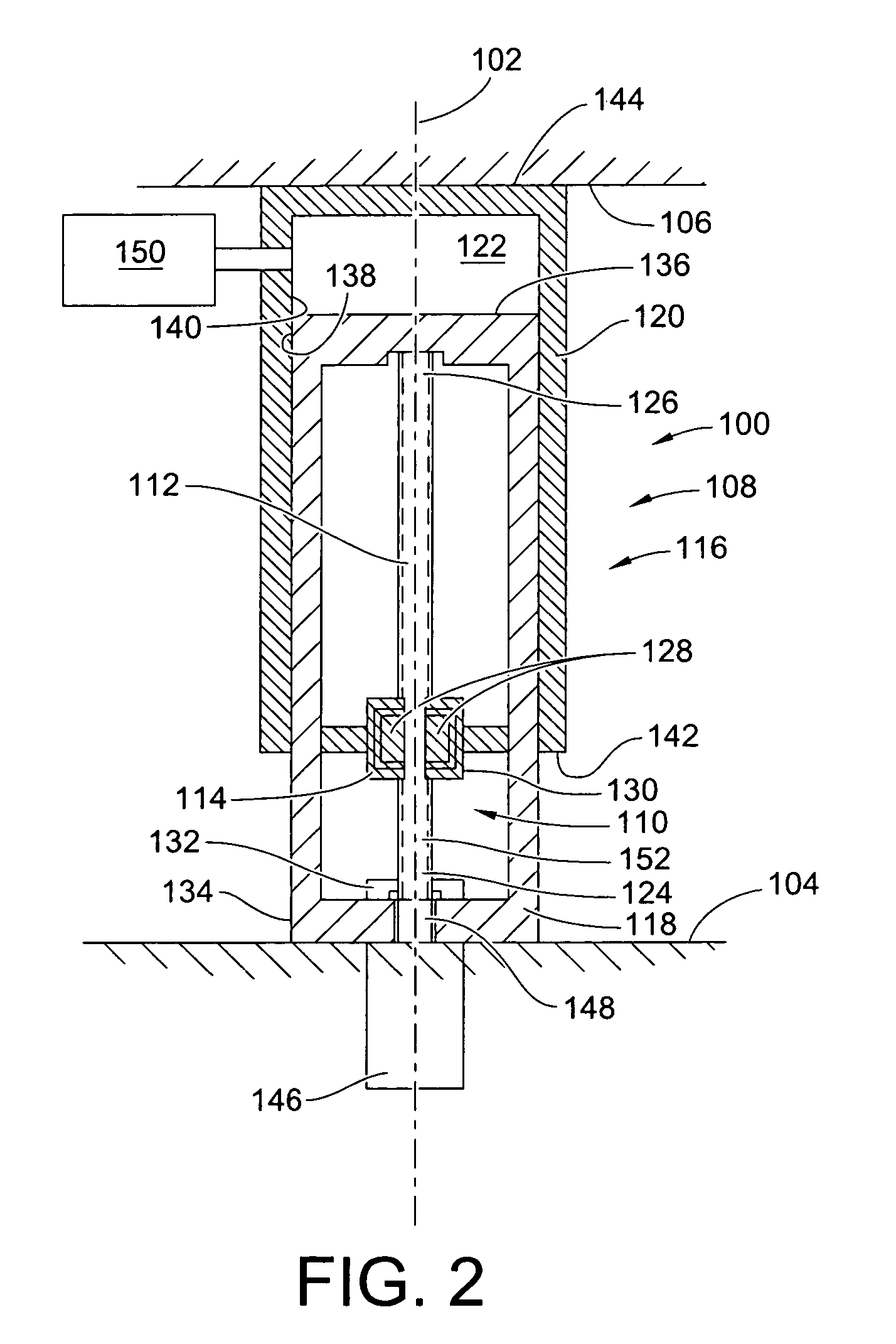
[0049]The pneumatic biasing arrangement 116, of the first exemplary embodiment 100, includes first and second cylinder elements 118, 120, which are connected to one another, for reciprocal movement with respect to one another along the axis of motion 102. The first and second cylinder elements 118, 120 are also configured for collectively defining a fluid cavity 122 between the first and second cylinder elements 118, 120, with the cavity 122 defining a volume for receiving a pressurized fluid.

[0050]The first cylinder element 118 is fixedly attached to the driving member 112. The second cylinder element 120 is fixedly attached to the driven member 114, for movement therewith along the axis of motion, such that relative movement of the driven and driving members 112, 114 with respect to one another in one direction along the axis of rotation causes an increase in the volume of the cavity 122, and movement of the driven and driving members with respect to one another in an opposite dir...

exemplary embodiment 200

[0074]FIGS. 4-6 illustrate a second exemplary embodiment of a pneumatically biasable mechanical linear actuator 200, according to the invention, which is substantially similar to the first exemplary embodiment of a linear actuator 108, described above, except that the second exemplary embodiment 200 includes a cavity volume and actuator minimum length adjusting element, in the form of a movable piston 202, disposed within the fluid cavity 204 of the actuator 200 for modifying the volume of the cavity 204. The volume adjusting piston 202 is attached to an extensible element 206 of a volume adjusting actuator 208 for moving the piston 202 axially up or down (when the actuator 200 is oriented as shown in FIGS. 2 and 3) to provide an additional mechanism for conveniently adjusting the working volume of the cavity 204, and thereby facilitate set up and use of the second exemplary embodiment of the linear actuator 200, when the operating load and / or operating force conditions, or the oper...

exemplary embodiment 520

[0089]Referring also to FIG. 11, in accordance with the invention, the pneumatically biasable mechanical linear actuator apparatus 521 for the mechanical press 520 includes a plurality of pneumatically augmented linear actuators 531-534 which support the movable platen 528 in overlying relationship with the fixed platen 524 and provide relative vertical movement between the fixed and movable platens. In general, the linear actuators 531-534, of the fifth exemplary embodiment 520 of the invention, are functionally and structurally substantially identical to the linear actuator 200 of the second exemplary embodiment of the invention 200, described above in relation to the schematic illustrations of FIGS. 2 and 3.

[0090]Preferably, one of the linear actuators 531-534 is provided near each corner 536 of the mechanical press 520. The linear actuators 531-534 are oriented vertically and have their lower ends connected to the base 522 and their upper ends connected to the movable platen 528...


PUM

PropertyMeasurementUnit
biasing forceaaaaaaaaaa
volumeaaaaaaaaaa
unidirectional biasing forceaaaaaaaaaa

Abstract

An improved method and apparatus are provided for constructing and operating a linear actuator, and equipment incorporating a linear actuator, by operatively connecting a pressure biasing pneumatic arrangement between the driving member and the driven member of a mechanical linear actuator for applying a unidirectional biasing force between the driving and driven members, along an axis of motion, regardless of the location or movement of the driving and driven elements with respect to one another along the axis of motion. The pneumatic biasing arrangement is also configured, connected and operated to reduce the force which must be exerted by the driving and driven members in extending and retracting the linear actuator. The pneumatic biasing arrangement may further be configured for preferentially aiding extension or retraction of the actuator.

Description

CROSS-REFERENCE TO RELATED PATENT APPLICATIONS[0001]This patent claims the benefit of U.S. Provisional Patent Application No. 60 / 720,592, filed Sep. 26, 2005, the disclosure of which is incorporated herein in its entirety by reference.FIELD OF THE INVENTION[0002]This invention relates to linear actuators, and more particularly to mechanical linear actuators, suitable for use in machinery such as metal forming presses, shears, brakes, and die cushions.BACKGROUND OF THE INVENTION[0003]Modem manufacturing practices often require machinery including linear actuators, for cutting, forming, punching, and / or joining together components formed from raw materials in a variety of forms, such as sheets, bar stock, billets, or pellet. Such machinery is often required to apply substantial compression loads, of, for example, 75 to 100 tons, and be capable of rapid cycle times, to promote efficient, effective, low cost production.[0004]High capacity machinery, of the type used in cutting and formi...

Claims


Application Information

Patent Timeline
Patent Type & Authority Patents(United States)
IPC IPC(8): F01B13/00F01B9/00
CPCB30B1/18B30B1/38Y10T74/1868B30B15/28F15B15/20
Inventor ANDERSON, ROBB G.MCCRICKARD, JAMES P.BECK, THOMAS L.
Owner UNICO LLC
Why Eureka
Try Eureka