Extended working range illumination system for an imaging-based bar code reader

an illumination system and bar code reader technology, applied in the field of can solve the problems of increasing the power requirements of the illumination system, wasting power by illuminating the entire field of view, and limiting the working range of prior art ccd and cmos imaging-based bar code readers, so as to avoid annoying ‘overspread’, reduce light pollution, and save power

Active Publication Date: 2010-07-06
SYMBOL TECH LLC
View PDF13 Cites 17 Cited by
  • Summary
  • Abstract
  • Description
  • Claims
  • Application Information

AI Technical Summary

Benefits of technology

[0009]The illumination source of the reading devices of the present disclosure are further capable of energizing to emit a novel second illumination pattern that is activated when a measured, estimated, or deduced distance to the target object is greater than a distance from which the first illumination pattern is capable of obtaining a sufficient reading of the target object. This second illumination pattern provides power effective illumination that increases the operable reading distance between the reader and the target object.
[0012]Another feature of the reader is the reduction of light pollution to the surrounding environment since the secondary illumination pattern is inactive during the reading or scanning of objects at a distance less than the system's threshold. A separate aspect of the reader narrows the illumination pattern by concentrating the pattern to a subset of the total FOV, thus saving power and avoiding annoying ‘overspread’ of intense illumination.

Problems solved by technology

The working range of prior art CCD and CMOS imaging-based bar code reader may be limited by the illumination system and ambient lighting.
Thus, as the target object distance is increased, the intensity required from the illumination system increases thereby increasing the power requirements of the illumination system.
Such a high intensity illumination system will waste power by illuminating the entire field of view unnecessarily when only a subset of the field of view (FOV) is necessary.

Method used


Image

  • Extended working range illumination system for an imaging-based bar code reader
  • Extended working range illumination system for an imaging-based bar code reader
  • Extended working range illumination system for an imaging-based bar code reader

Examples


Embodiment Construction

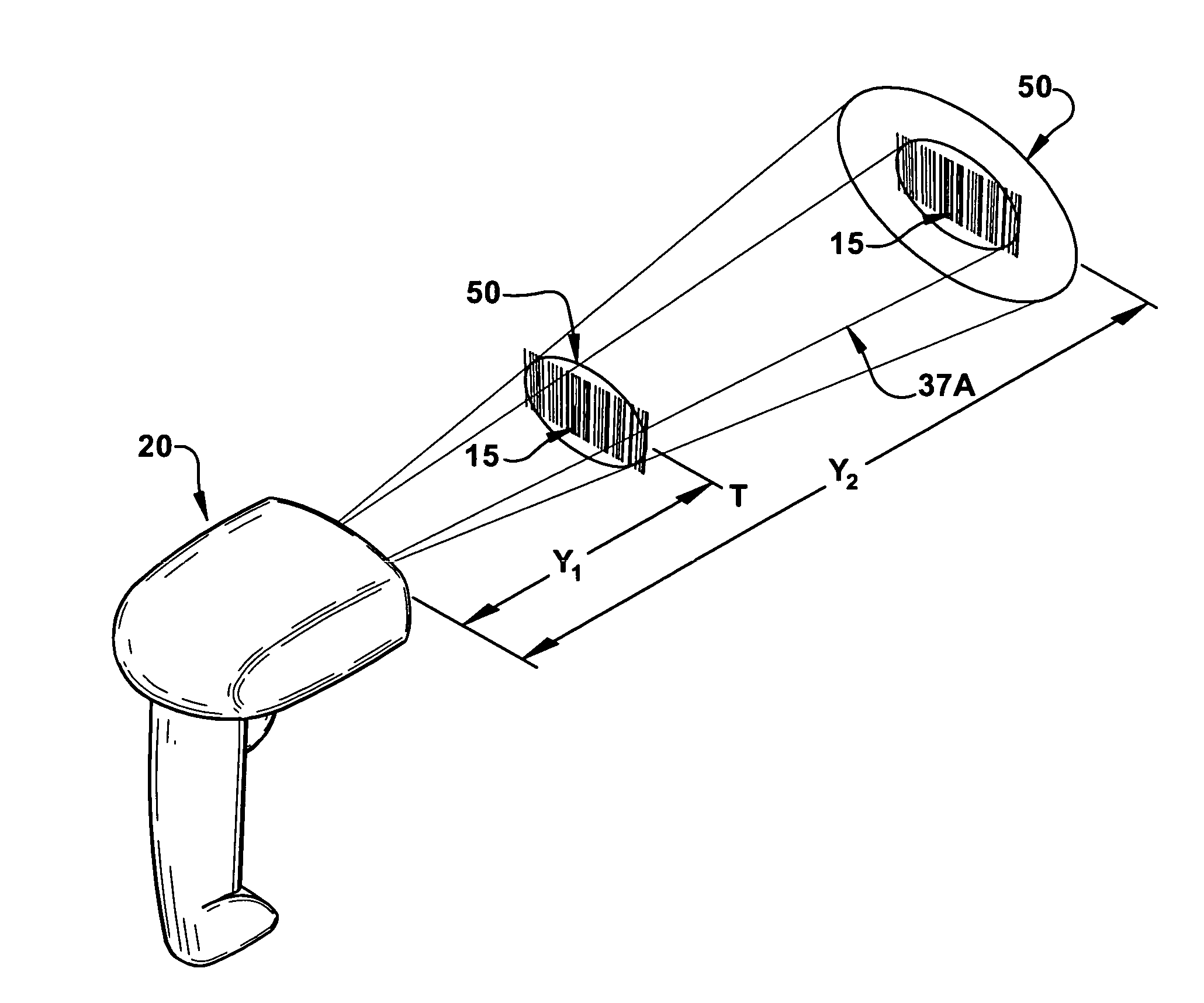
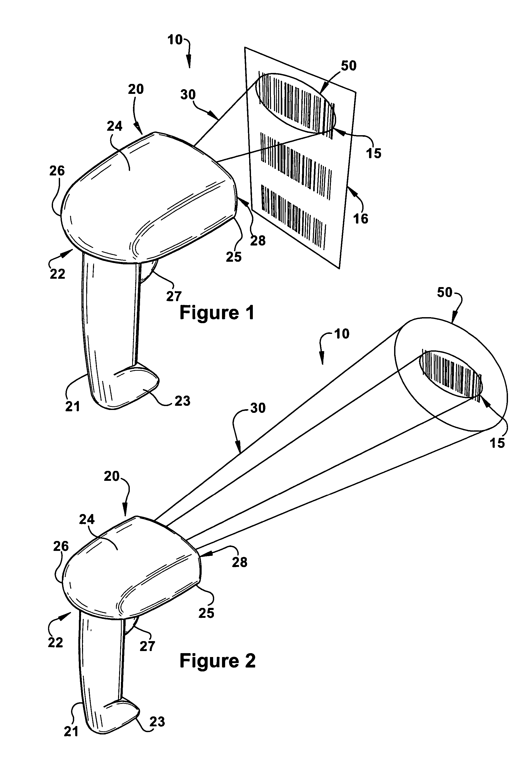
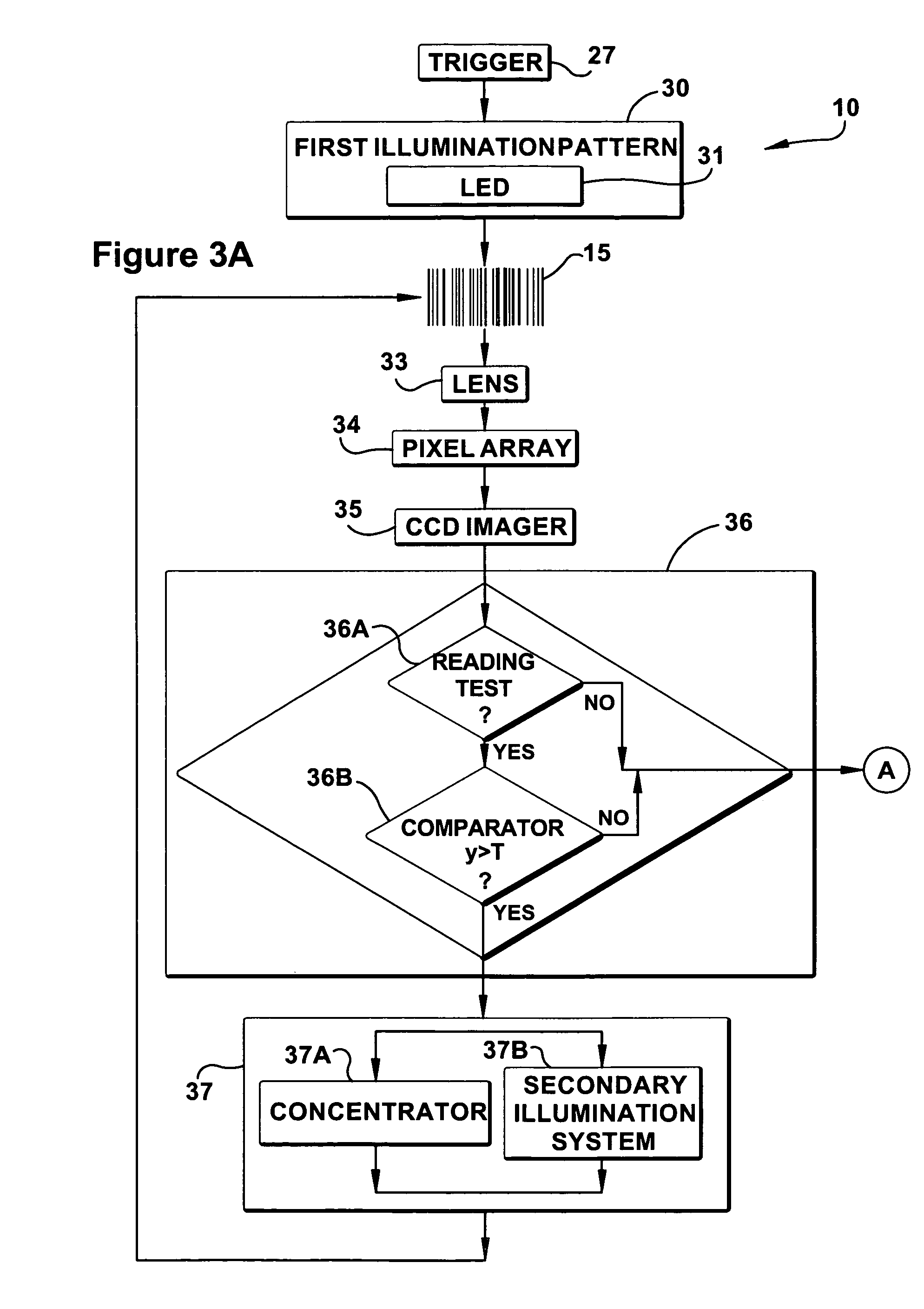
[0024]An imaging-based reading system is shown schematically at 10 in FIGS. 1 through 4B. A typical profile of a portable bar code reader 20 is physically shown in FIGS. 1, 2, 4A, and 4B. In addition to imaging and decoding 1D and 2D bar codes, including postal codes, and Code 39 bar codes, the reading system 10 is also capable of capturing images and signatures. In a preferred embodiment of the present invention, the bar code reader 20 is a hand held portable reader that can be carried and used by a user walking or riding through a store, warehouse, or plant, while reading bar codes for stocking and inventory control purposes.

[0025]However, it should be recognized that the imaging-based bar code reader 20 of the present invention, to be explained below, may be advantageously used in connection with any type of imaging-based automatic identification system including, but not limited to, bar code scanners, signature imaging acquisition and identification systems, optical character re...


PUM


Abstract

A method and apparatus for reading a target object having areas of differing light reflectivity on the target such as a handheld bar code reader having a first illumination pattern, a detector for measuring a distance from the reader to a target object, a system threshold, and a comparator for evaluating the measured distance against the threshold. Should the reader's internal circuitry and / or software determine that the measured distance is greater than the threshold, a second illumination pattern is activated that has power effective illumination for increasing the operable reading distance between the reader and the target object. The second illumination pattern can be generated from a secondary illumination source or through a lens internal to the reader.

Description

FIELD OF THE INVENTION[0001]The present invention relates to an illumination system for an imaging-based bar code reader and, more particularly, to an illumination system for an imaging-based bar code reader having an enhanced illumination source that is selectively actuated to increase an effective working range of the reader.BACKGROUND ART[0002]Various electro-optical systems have been developed for reading optical indicia, such as bar codes. A bar code is a coded pattern of graphical indicia comprised of a series of bars and spaces of varying widths, the bars and spaces having differing light reflecting characteristics. Some of the more popular bar code symbologies include: Uniform Product Code (UPC), typically used in retail stores sales; Code 39, primarily used in inventory tracking; and Postnet, which is used for encoding zip codes for U.S. mail. Systems that read and decode bar codes employing charged coupled device (CCD) or complementary metal oxide semiconductor (CMOS) base...

Claims


Application Information

Patent Timeline
Patent Type & Authority Patents(United States)
IPC IPC(8): G06K7/10
CPCG06K7/10554G06K7/10801
Inventor BROCK, CHRISTOPHER
Owner SYMBOL TECH LLC
Why Eureka
Try Eureka