Electrical Connector
- Summary
- Abstract
- Description
- Claims
- Application Information
AI Technical Summary
Benefits of technology
Problems solved by technology
Method used
Image

Examples
Embodiment Construction
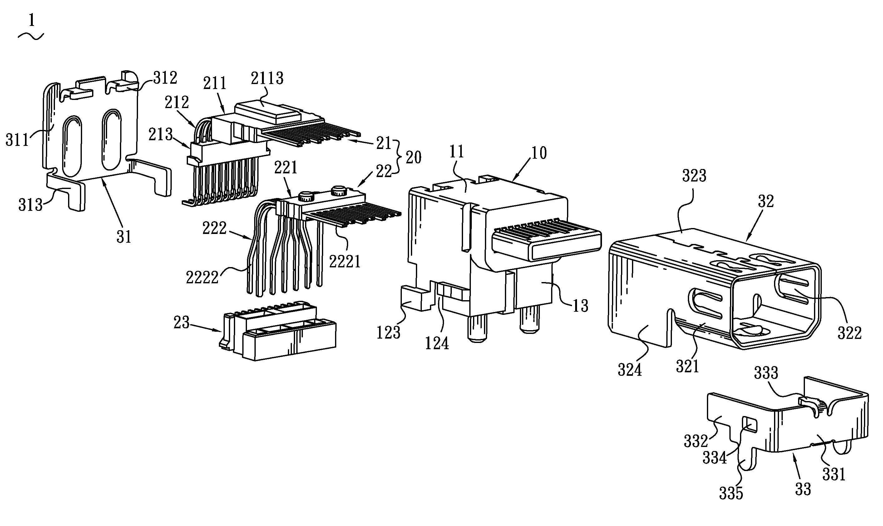
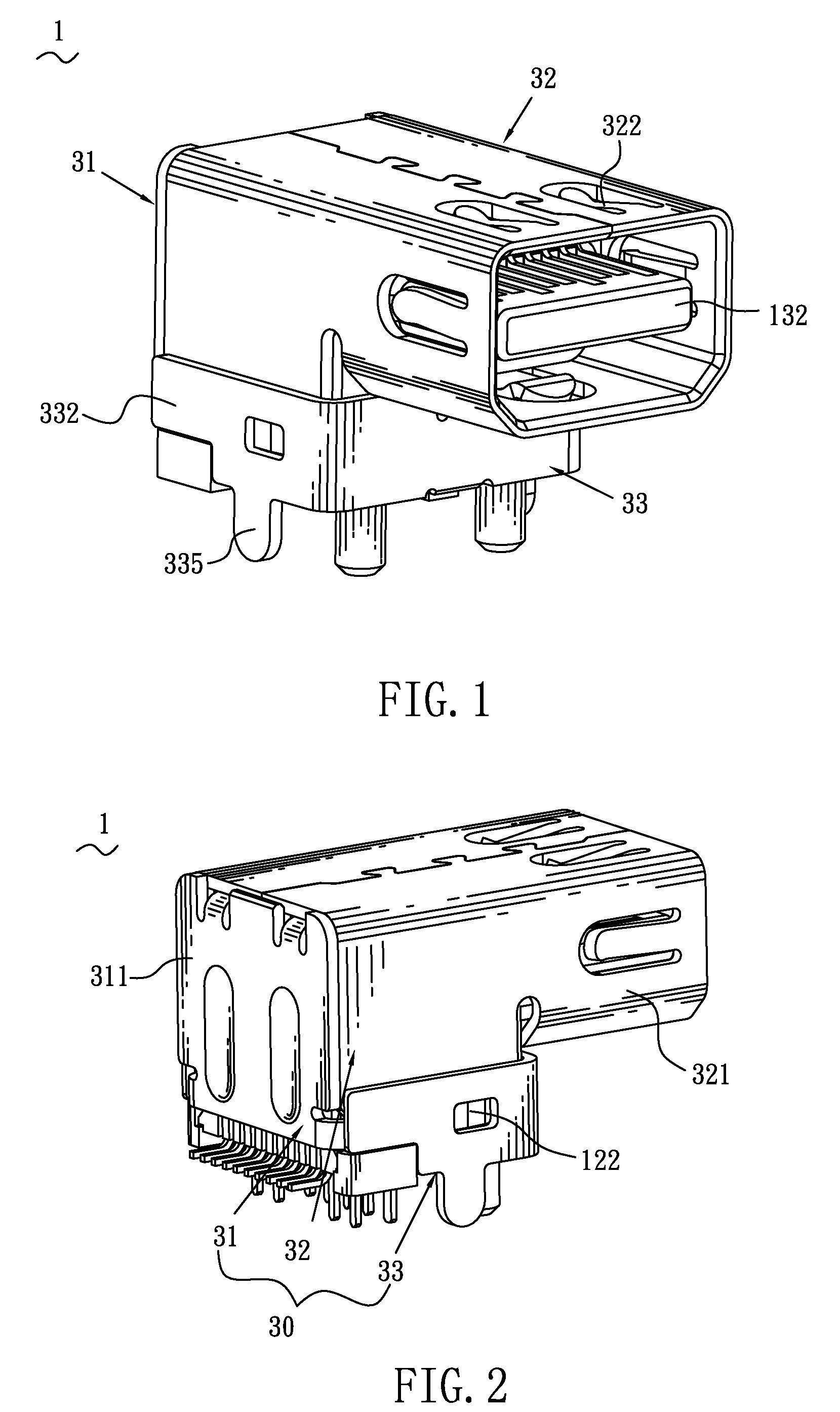
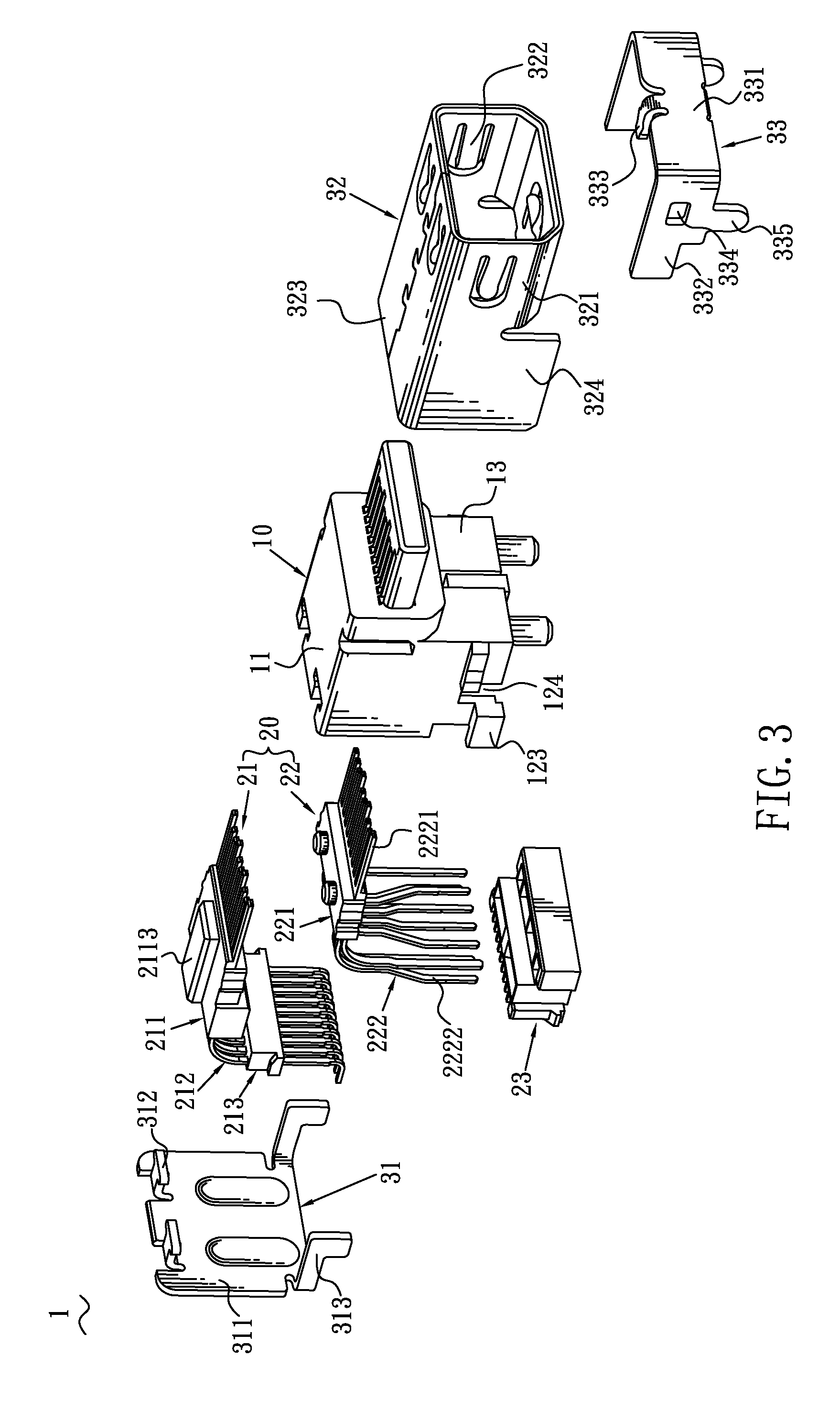
[0021]Please refer to FIGS. 1-3, an electrical connector 1 according to the present invention is shown. The electrical connector 1 includes an insulating housing 10, a terminal module 20 disposed in the insulating housing 10 and a shielding shell 30 enclosed a periphery of the insulating housing 10.
[0022]Please refer to FIG. 4 and FIG. 5, the insulating housing 10 includes a rectangular top wall 11, two opposite lateral walls 12 perpendicularly extended downwards from two lateral edges of the top wall 11, a front wall 13 extended downwards from a front edge of the top wall 11 and connected with the lateral walls 12, forming a receiving chamber 40 for receiving the terminal module 20.
[0023]The top wall 11 has two T-shaped fixing recesses 111. The fixing recesses 111 are arranged at a rear end of a top surface of the top wall 11 and reach a rear surface of the top wall 11. A bottom surface of the top wall 11 is concaved upwards to form a guiding recess 112. The guiding recess 112 is l...
PUM
 Abstract
Description
Claims
Application Information
 - Generate Ideas
- Intellectual Property
- Life Sciences
- Materials
- Tech Scout
- Unparalleled Data Quality
- Higher Quality Content
- 60% Fewer Hallucinations
Browse by: Latest US Patents, China's latest patents, Technical Efficacy Thesaurus, Application Domain, Technology Topic, Popular Technical Reports.
© 2025 PatSnap. All rights reserved.Legal|Privacy policy|Modern Slavery Act Transparency Statement|Sitemap|About US| Contact US: help@patsnap.com