Chemical vapor deposition apparatus

a technology of chemical vapor and vapor deposition, which is applied in the direction of chemical vapor deposition coating, coating, metallic material coating process, etc., can solve the problems of difficult to grow high-quality thin films on wafers, inability to implement uniform flow of reaction gas, and relatively low crystal growth speed, etc., to achieve high-quality thin films

a technology of chemical vapor and vapor deposition, which is applied in the direction of chemical vapor deposition coating, coating, metallic material coating process, etc., can solve the problems of difficult to grow high-quality thin films on wafers, inability to implement uniform flow of reaction gas, and relatively low crystal growth speed, etc., to achieve high-quality thin films

US7749326B2Inactive Publication Date: 2010-07-06SAMSUNG ELECTRONICS CO LTD

Image

  • Chemical vapor deposition apparatus
  • Chemical vapor deposition apparatus
  • Chemical vapor deposition apparatus

Examples


Embodiment Construction

[0033]Reference will now be made in detail to the embodiments of the present general inventive concept, examples of which are illustrated in the accompanying drawings, wherein like reference numerals refer to like elements throughout. The embodiments are described below in order to explain the present general inventive concept by referring to the figures.

[0034]Hereinafter, a chemical vapor deposition apparatus according to the present invention will be described in detail with reference to the accompanying drawings.

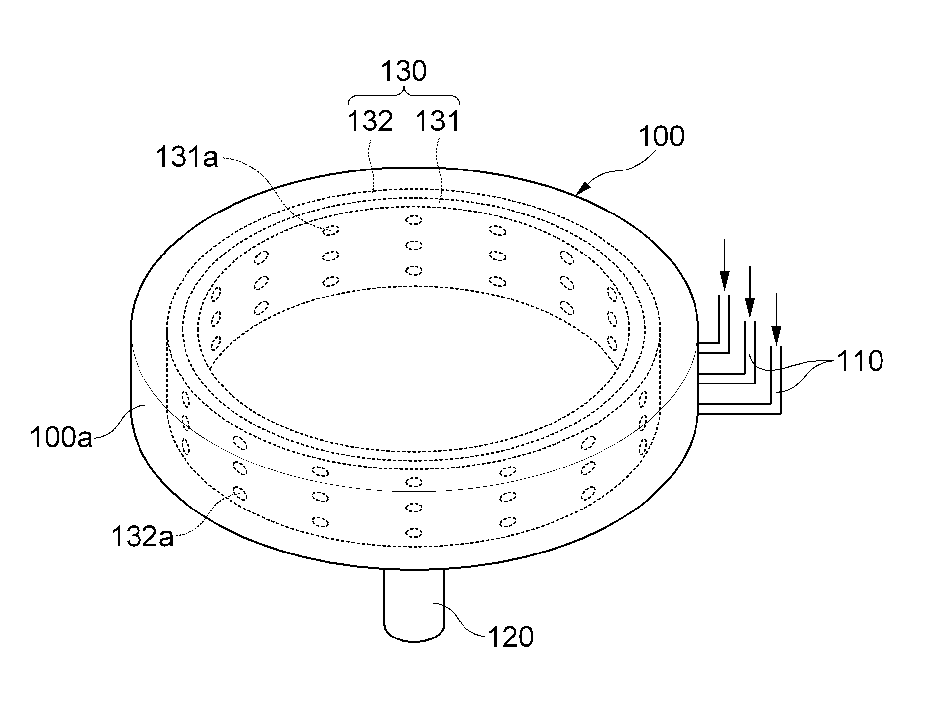
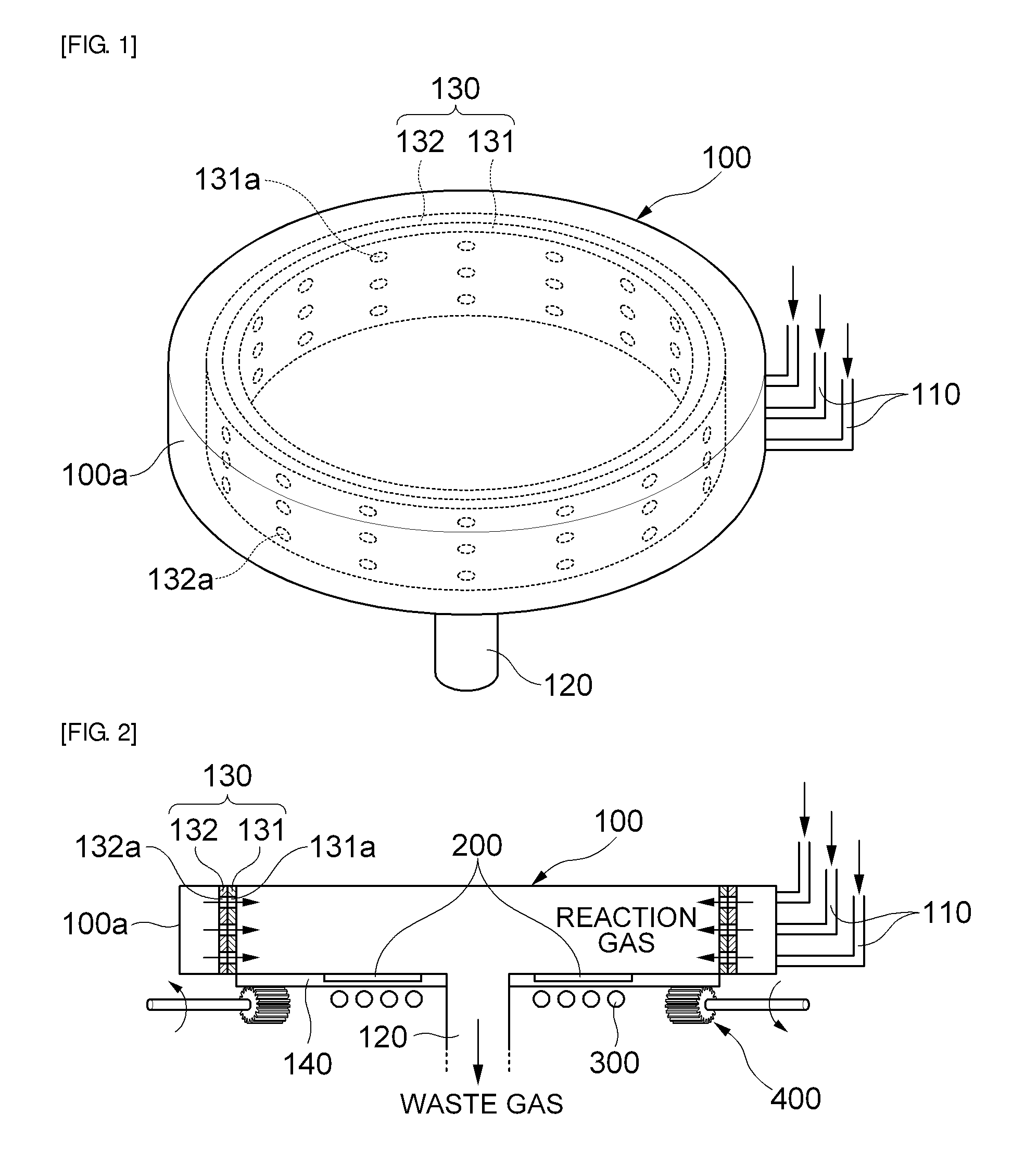
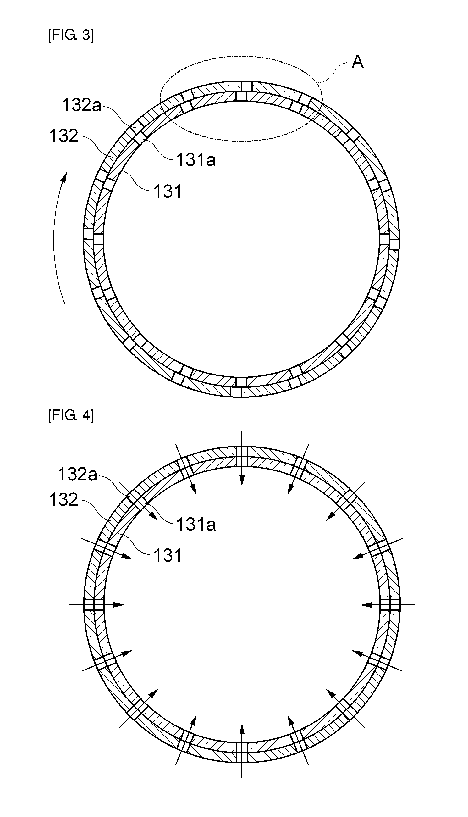
[0035]FIG. 1 is a schematic perspective view of a chemical vapor deposition apparatus according to an embodiment of the invention. FIG. 2 is a schematic cross-sectional view of the chemical vapor deposition apparatus according to the embodiment of the invention. FIG. 3 is a schematic cross-sectional view of a variable gas-flow adjusting unit of FIG. 2. FIG. 4 is a diagram showing a state where the area of overlapping holes is maximized by rotating an inner gas jetting pla...


PUM

PropertyMeasurementUnit
areaaaaaaaaaaa
inclination angleaaaaaaaaaa
shapeaaaaaaaaaa

Abstract

Provided is a chemical vapor deposition apparatus including a reaction chamber; a susceptor that is provided in the reaction chamber and has a plurality of wafers mounted thereon; a rotation driving unit that rotates the susceptor; a gas inlet that is provided in the reaction chamber and introduces reaction gas into the reaction chamber from the outside of the reaction chamber; a gas outlet that is provided in the reaction chamber and discharges the reaction gas, of which the reaction is finished, from the inside of the reaction chamber along the rotation-axis direction of the susceptor; and a variable gas-flow adjusting unit that is provided between the gas inlet and the gas outlet and is formed by superimposing a plurality of gas jetting plates having a plurality of holes.

Description

CROSS-REFERENCE TO RELATED APPLICATIONS[0001]This application claims the benefit of Korean Patent Application No. 10-2008-0047510 filed with the Korea Intellectual Property Office on May 22, 2008, the disclosure of which is incorporated herein by reference.BACKGROUND OF THE INVENTION[0002]1. Field of the Invention[0003]The present invention relates to a chemical vapor deposition apparatus which includes a variable gas-flow adjusting unit which uniformly distributes reaction gas introduced into a reaction chamber.[0004]2. Description of the Related Art[0005]In general, CVD (Chemical Vapor Phase Deposition) is mainly used for growing various crystal films on various substrates.[0006]Compared with LPE (Liquid Phase Epitaxy), the quality of crystal grown by CVD is excellent, but the growth speed of crystal is relatively low.[0007]To overcome such a problem, a growth method is widely adopted, in which films are simultaneously grown on several substrates in one growth cycle.[0008]However,...

Claims


Application Information

Patent Timeline
06 Jul 2010
Publication
US7749326B2
IPC
C23C16/455; C23F1/00; H01L21/306; C23C16/458; C23C16/06; C23C16/22
CPC
C23C16/45508; C23C16/45512; C23C16/45589; H01L21/68771; C23C16/4584
Inventors
KIM, CHANG SUNG SEAN; HONG, JONG PA