Instantaneous voltage-drop compensation circuit, power conversion apparatus, instantaneous voltage-drop compensation method and computer readable medium storing instantaneous voltage-drop compensation program

a compensation circuit and voltage drop technology, applied in emergency power supply arrangements, instruments, process and machine control, etc., can solve the problems of high cost, device requires a large equipment, voltage drops sometimes occuring in three-phase balanced or unbalanced states, etc., to achieve easy maintenance of the system, reduce the cost, and prolong the life

Active Publication Date: 2010-07-06
KYOSAN ELECTRIC MFG CO LTD
View PDF13 Cites 20 Cited by
  • Summary
  • Abstract
  • Description
  • Claims
  • Application Information

AI Technical Summary

Benefits of technology

[0021]According to the invention, the instantaneous voltage-drop compensation can be achieved by converting AC input power itself. This allows the structure for the instantaneous voltage-drop compensation to be smaller with longer life at lower cost, and also allows easier maintenance of the system. Further, this compensation improves the power factor, allowing harmonics suppression with the power factor correction.
[0034]According to the compensation circuit having such a configuration, response of the input current command signal to the fluctuation of AC input voltage can be made speedier. This allows suppression of transient change of the DC output voltage.
[0040]According to the compensation circuit having such a configuration, response to the load change of the load to which the DC output power is output can be made speedier. This allows suppression of transient change of the DC output voltage.
[0053]According to the second aspect of the invention, the instantaneous voltage-drop compensation can be achieved by converting AC input power itself. This allows the structure for the instantaneous voltage-drop compensation to be smaller with longer life at lower cost, and also allows easier maintenance of the system. Further, this compensation improves the power factor, allowing harmonics suppression with the power factor correction.
[0064]According to the third aspect of the invention, the instantaneous voltage-drop compensation can be achieved by converting AC input power itself. This allows the structure for the instantaneous voltage-drop compensation to be smaller with longer life at lower cost, and also allows easier maintenance of the system. Further, this compensation improves the power factor, allowing harmonics suppression with the power factor correction.
[0099]According to the fourth aspect of the invention, the instantaneous voltage-drop compensation can be achieved by converting AC input power itself. This allows the structure for the instantaneous voltage-drop compensation to be smaller with longer life at lower cost, and also allows easier maintenance of the system. Further, this compensation improves the power factor, allowing harmonics suppression with the power factor correction.

Problems solved by technology

Three-phase AC is generally connected not only to three-phase equal loads but also to various single-phase loads, however, voltage drops have sometimes occurred in three-phase balanced or unbalanced states under various influences from turn-on of a load, weather, accidental phenomena, or the like.
In the configuration using the power storage device, such as a condenser or a secondary battery, as in the conventional power conversion apparatus 100B, the power storage device requires a large equipment and makes its cost higher.
Further, the power storage device has required measures for deterioration with time, had comparatively short apparatus life, and made maintenance load larger.

Method used


Image

  • Instantaneous voltage-drop compensation circuit, power conversion apparatus, instantaneous voltage-drop compensation method and computer readable medium storing instantaneous voltage-drop compensation program
  • Instantaneous voltage-drop compensation circuit, power conversion apparatus, instantaneous voltage-drop compensation method and computer readable medium storing instantaneous voltage-drop compensation program
  • Instantaneous voltage-drop compensation circuit, power conversion apparatus, instantaneous voltage-drop compensation method and computer readable medium storing instantaneous voltage-drop compensation program

Examples


first embodiment

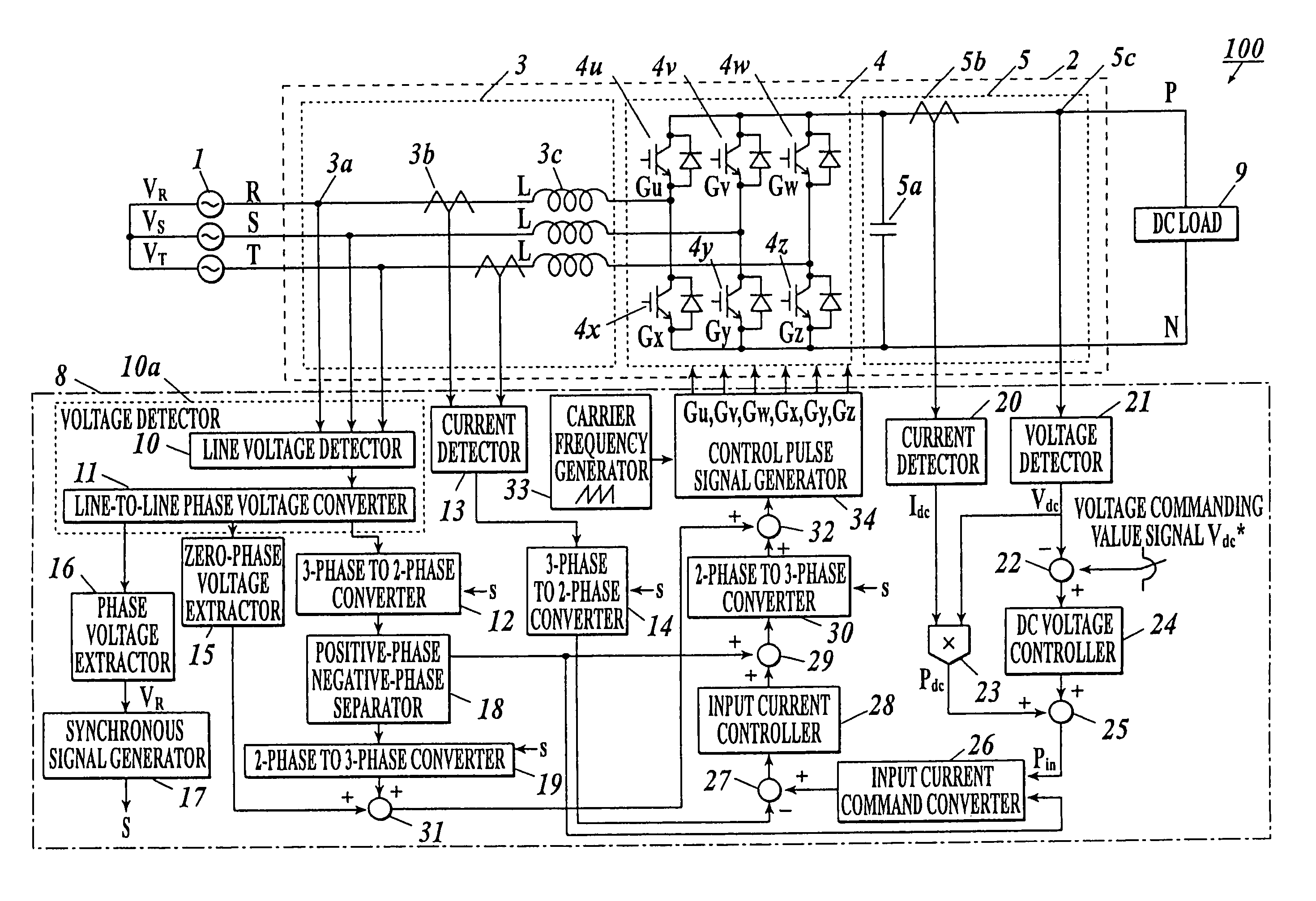
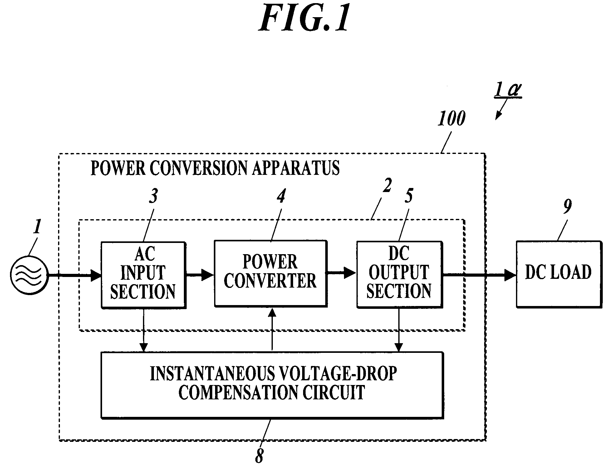
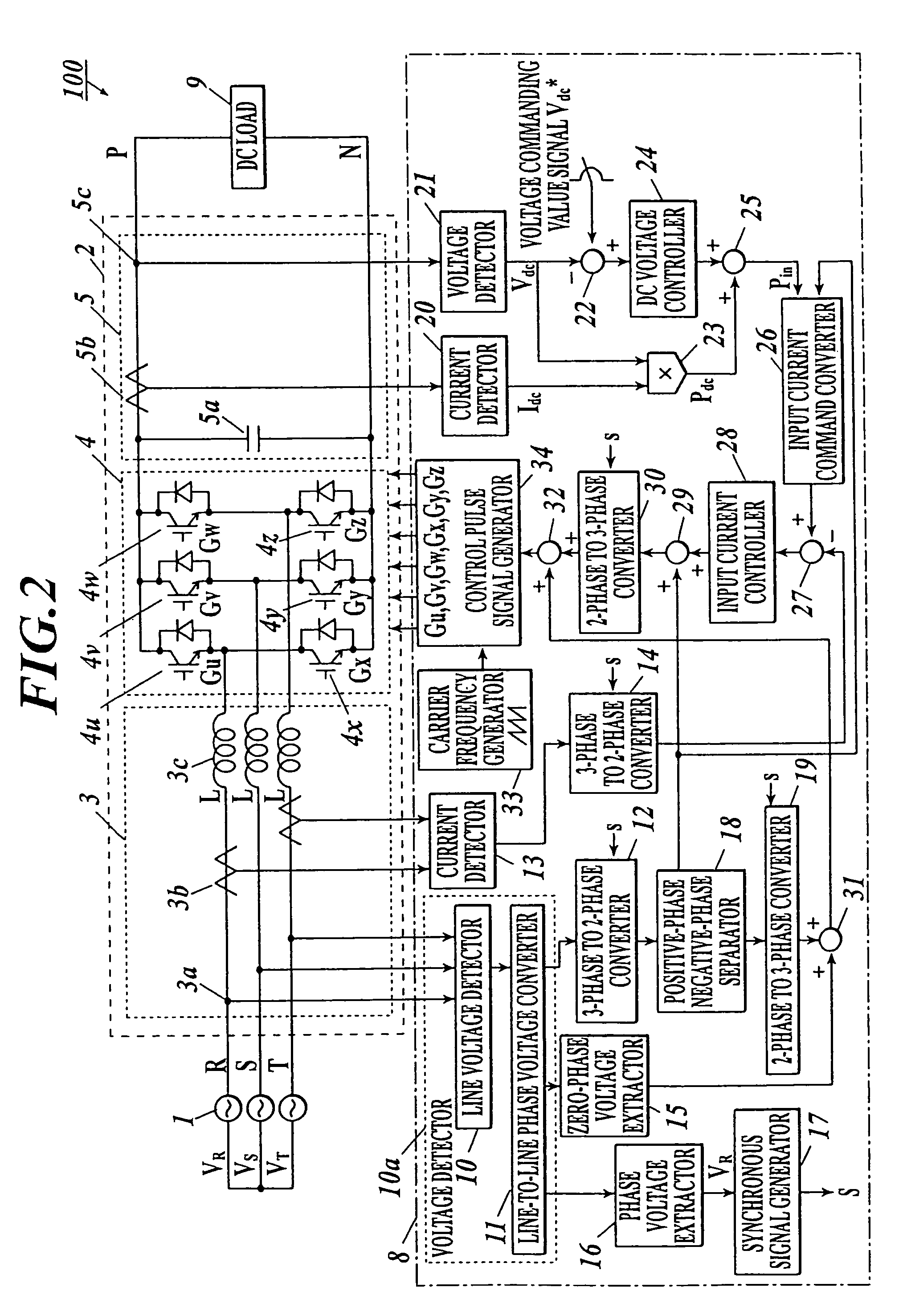
[0135]The first embodiment according to the invention will be described with reference to FIGS. 1 to 3. FIG. 1 shows a configuration of a power conversion system 1α of the present embodiment.

[0136]Referring first to FIGS. 1 and 2, the structure of an apparatus of the embodiment will be described. As shown in FIG. 1, the power conversion system 1α includes a three-phase AC power source 1, a power conversion apparatus 100, and a DC load 9.

[0137]The three-phase AC power source 1 is three-phase AC input power source alternating with an angular frequency ω. The DC load 9 is a load for direct current. The power conversion apparatus 100 includes a main circuit section 2, and an instantaneous voltage-drop compensation circuit 8. The main circuit section 2 is a circuit that converts the three-phase AC power input from the AC power source 1 into DC power. The main circuit section 2 includes an AC input section 3, a power converter 4, and a DC output section 5.

[0138]The AC input section 3 rece...

first modification

(First Modification)

[0205]A first modification of the above-described first embodiment will be explained.

[0206]In the power conversion apparatus 100 of the first embodiment, when the AC input voltage instantaneously drops, the calorific value of power conversion elements increases because of increase of the input current. In an instantaneous time (0.5-5 sec) normally defined, the cooling function of the power conversion apparatus 100 need not be intensified. However, if the input voltage largely drops for a long time, the calorific value of power conversion elements increases proportionally to the power.

[0207]For solving this problem, a power conversion apparatus 100 of this modification is provided with a cooling device, such as a fan, for cooling the power conversion elements. By intensifying the cooling function for the power conversion elements by the cooling device, stable power can be supplied to the DC load 9 even when the input voltage largely drops for a long time, and a po...

second modification

(Second Modification)

[0209]A second modification of the first embodiment will be described with reference to FIG. 4. FIG. 4 shows a power conversion system 1β of this modification.

[0210]As shown in FIG. 4, the power conversion system 1β includes three-phase AC power source 1, power conversion apparatus 100, DC / AC conversion circuit 200, and three-phase AC loads 9A. The DC / AC conversion circuit 200 is an inverter or the like, and includes transistors 201-206 having respective diodes. The three-phase AC loads 9A are loads to which three-phase AC power is input.

[0211]The DC / AC conversion circuit 200 converts the DC output power output from the power conversion apparatus 100 to the three-phase AC output power with on / off control of respective gates of the transistors 201-206, and supplies the power to the three-phase AC loads 9A.

[0212]According to the modification, even when the input voltage instantaneously drops, stable power can be supplied to the three-phase AC loads 9A, and a three...


PUM


Abstract

An instantaneous voltage-drop compensation circuit including: a first voltage detector detecting three-phase voltages to be input to a power converter converting three-phase AC to DC based on control pulse signals, and outputting three-phase voltage signals; a first three-phase to two-phase converter converting the detected signals to two-phase voltage signals; a first current detector detecting three-phase currents to be input to the power converter and outputting three-phase current signals; a second three-phase to two-phase converter converting the detected current signals to two-phase current signals; a first subtracter generating a first deviation signal from input current command signals and the two-phase current signals; an input current controller generating input current control signals based on the first deviation signal; and a first adder adding the two-phase voltage signals to the input current control signals, to generate control pulse signals for the power converter.

Description

BACKGROUND OF THE INVENTION[0001]1. Field of the Invention[0002]The present invention relates to an instantaneous voltage-drop compensation circuit, a power conversion apparatus, an instantaneous voltage-drop compensation method and a computer readable medium storing an instantaneous voltage-drop compensation program.[0003]2. Description of the Related Art[0004]There has been commonly used an (AC-DC) power conversion apparatus which converts three-phase alternating current (AC) power to direct current (DC) power. In this power conversion apparatus, there has been also used an instantaneous voltage-drop compensation apparatus which can maintain power supply to a load, particularly when three-phase AC input voltage fails or drops instantaneously (see, for example, Patent Document 1: JP 2004-222447A).[0005]FIG. 9 shows a configuration of a conventional power conversion system 1ζ. As shown in FIG. 9, the power conversion system 1ζ includes a three-phase AC power source 1, a power conver...

Claims


Application Information

Patent Timeline
Patent Type & Authority Patents(United States)
IPC IPC(8): H02M7/217
CPCH02M7/125H02J3/12H02J9/06
Inventor YUZURIHARA, ITSUOTAKAYANAGI, ATSUSHITAKAMURA, RYUICHI
Owner KYOSAN ELECTRIC MFG CO LTD
Why Eureka
Try Eureka