Full duplex network radio bridge with low latency and high throughput

a network radio and duplex technology, applied in the field of full duplex network radio bridges with low latency and high throughput, can solve the problems of short return on investment and high cost of high-speed data over lines owned by phone companies or other entities

Inactive Publication Date: 2010-07-06
PABST WILLIAM GEORGE
View PDF3 Cites 29 Cited by
  • Summary
  • Abstract
  • Description
  • Claims
  • Application Information

AI Technical Summary

Problems solved by technology

Networking of high speed data over lines owned by the phone companies or other entities is expensive.
Since the costs are low, the return on investment is short.

Method used


Image

  • Full duplex network radio bridge with low latency and high throughput
  • Full duplex network radio bridge with low latency and high throughput
  • Full duplex network radio bridge with low latency and high throughput

Examples


Embodiment Construction

[0019]Prior art systems offered by Airaya and other companies such as Cisco, Proxim, Redline, etc. are all half duplex except for a full duplex product offered by Tranzio. Half duplex means that the radio transceivers on each end are limited such that only one end can transmit at any particular time. Half duplex limits the data rate because all the devices connected to the radio bridges are Ethernet devices which have full duplex capability which is wasted.

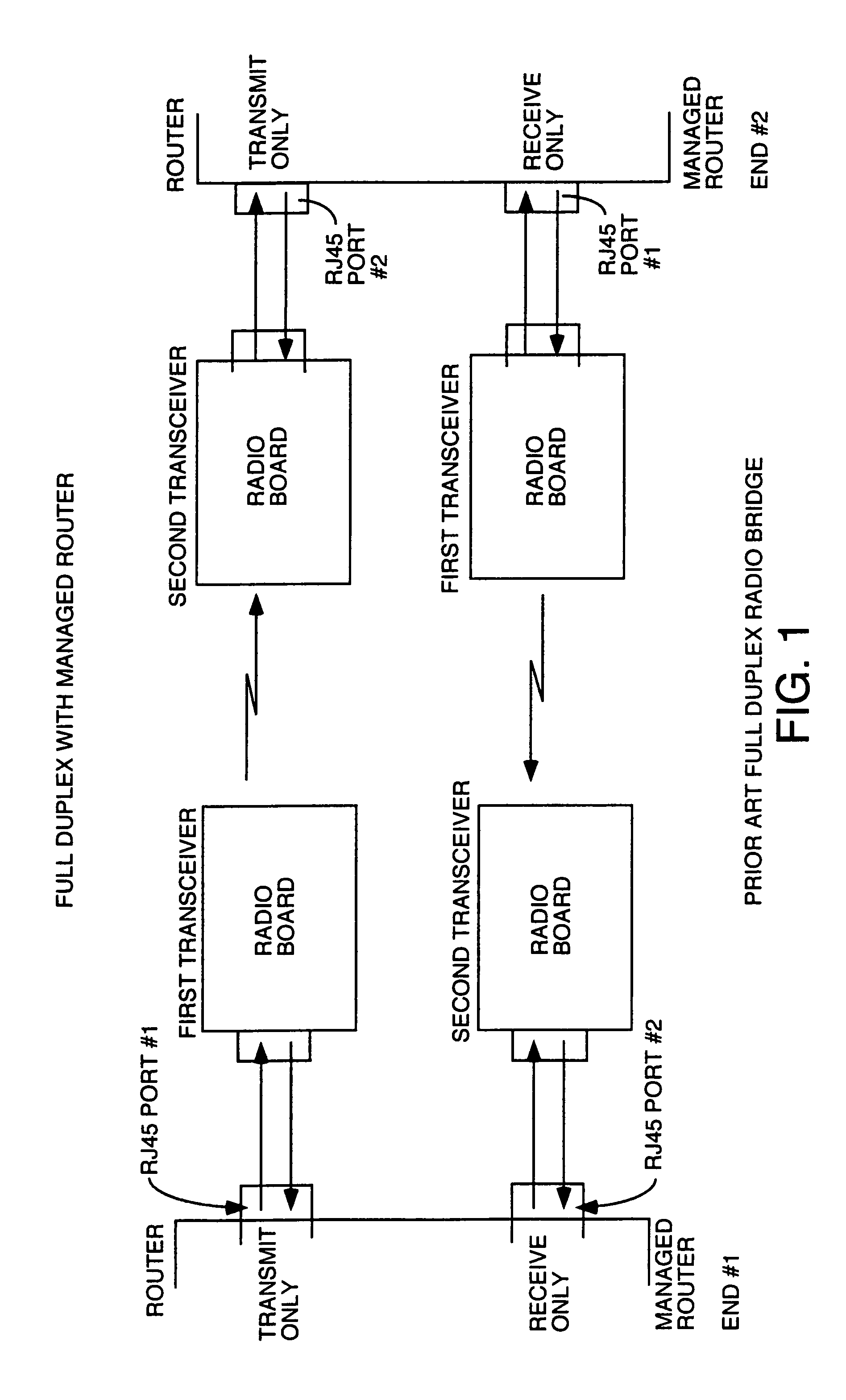
[0020]Some attempts at full duplex have been made where two separate radio links are used and a commercial level gateway approximately $10,000 to $30,000 for these commercial level gateways is used at each end of the radio bridge. Such a prior art system is shown in FIG. 1. Let's call the two ends end #1 and end #2. At end #1 there is a first half duplex downstream radio board having a half duplex transceiver the first transceiver which is transmitting data downstream. This radio bridge has an RJ45 Ethernet port which is coupled t...


PUM


Abstract

A full duplex radio bridge using two transceivers coupled to a first packet network, one for transmitting data toward another radio bridge coupled to a second packet network, and the other for receiving data transmitted from the first packet network toward said second packet network by a transceiver of the other radio bridge. Each radio bridge is coupled to its packet network through one network port whose transmit data path is coupled to one of the transceivers, and whose receive data path is coupled to receive data from the other transceiver. An inner loop and outer loop is used. Management packets are routed to the various transceivers using the inner loop and outer loop by routing and filtering functions. Payload packets are transmitted from one packet network to the other using only the outer loop.

Description

BACKGROUND OF THE INVENTION[0001]Networking of high speed data over lines owned by the phone companies or other entities is expensive. Some customers want to network high speed data and own their own infrastructure by sending the data line-of-sight by RF between antennas located at high points that are in line of sight of other antennas. This saves these customers quite a bit of money since they have no recurring fees, and the customers can manage and control their network infrastructure themselves. Since the costs are low, the return on investment is short.BRIEF DESCRIPTION OF THE SEVERAL VIEWS OF THE DRAWINGS[0002]FIG. 1 is a block diagram of a prior art radio bridge system using two half duplex radio transceivers at each end, each coupled to a managed router.[0003]FIG. 2 is a block diagram of illustrating the loop problem.[0004]FIG. 3 is a block diagram of one embodiment of an Ethernet radio bridge which solves the loop problem and which does not require either a managed hub or c...

Claims


Application Information

Patent Timeline
Patent Type & Authority Patents(United States)
IPC IPC(8): H04B3/30
CPCH04W88/14H04L5/14
Inventor PABST, WILLIAM GEORGE
Owner PABST WILLIAM GEORGE
Why Eureka
Try Eureka