Ink jet printing apparatus and ink jet printing method

a printing apparatus and ink jet technology, applied in printing, other printing apparatus, etc., can solve the problems of affecting the ejection operation of ink, image quality, image density variation, etc., to reduce the ejection speed of ink, and increase the viscosity of ink

Inactive Publication Date: 2010-07-13
CANON KK
View PDF10 Cites 2 Cited by
  • Summary
  • Abstract
  • Description
  • Claims
  • Application Information

AI Technical Summary

Benefits of technology

[0016]The first aspect of the present invention is an ink jet printing apparatus for forming an image by using a print head, wherein the print head has a plurality of printing elements for a plurality of inks with different viscosities, wherein the printing elements eject ink when applied a voltage pulse, the ink jet printing apparatus comprising: a drive adjust means to adjust a waveform of the voltage pulse, for each of the plurality of inks, in a way that reduces an ejection speed of ink as the viscosity of ink increases.
[0017]The second aspect of the present invention is an ink jet printing method for forming an image by using a print head, wherein the print head has a plurality of printing elements for a plurality of inks with different viscosities, wherein the printing elements eject ink when applied a voltage pulse, the ink jet printing method comprising the step of: adjusting a waveform of the voltage pulse, for each of the plurality of inks, in a way that reduces an ejection speed of ink as the viscosity of ink increases.

Problems solved by technology

However, since pigments are not as easily soluble as dyes, appropriate dispersion processing or technique is required for uniformly dispersing pigment particles in a solvent and keeping them in the dispersed state.
However, as the ink droplets are being progressively reduced in size in recent years, some instances have been recognized in which differences in physical property among different color inks have come to affect the ink ejection operation and even the image quality.
As a result, in an ink jet printing apparatus that forms a color image using a plurality of inks with different physical properties, the dot landing deviations cause image density variations and color deviations, degrading the printed image.
As described above, in an ink jet printing apparatus of recent years that forms an image by using small drops of color inks, differences in physical property among inks translate into differences in the ejection characteristic, which in turn degrades an image quality.
Such an image problem caused by the ejection speed difference between the main drop and its satellite has newly been brought to the fore by the rapid size reduction of ink droplets in recent years.
This is because as the main drop becomes smaller, the presence of the satellite becomes more significant, making the printing position deviations of these drops more likely to affect the image being printed.

Method used


Image

  • Ink jet printing apparatus and ink jet printing method
  • Ink jet printing apparatus and ink jet printing method
  • Ink jet printing apparatus and ink jet printing method

Examples


first embodiment

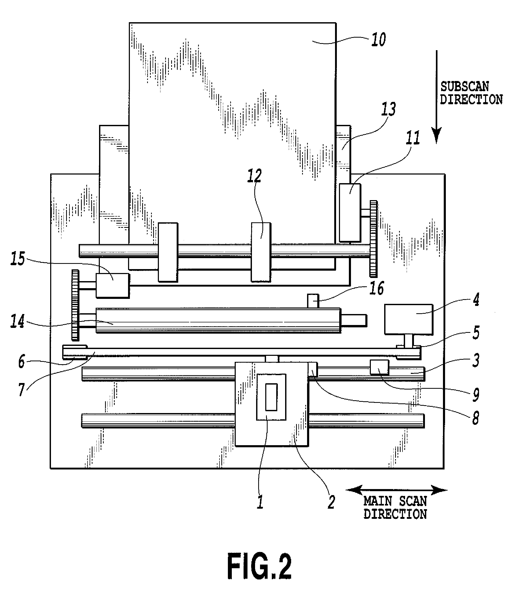
[0036]FIG. 2 shows the construction of an essential part of a serial type ink jet printing apparatus applied in this embodiment. A drive force of a carriage motor 4 is transmitted through a motor pulley 5, a follower pulley 6 and a timing belt 7 to a carriage 2, which, with the print head cartridge 1 mounted on it, executes reciprocal scans in the main scan direction, guided and supported by a guide shaft 3 extending in the main scan direction. The carriage 2 has a home position sensor 8 at one end thereof which, when it moves past the position of a shield plate 9, detects that the carriage 2 is at the home position. Though not shown, in an area where a printing operation is performed by the print head cartridge 1 mounted on the carriage 2 there is arranged a platen that supports a print medium from below. The print medium on the platen is thus horizontally flat so that a distance between a nozzle face of the print head and the print medium is kept constant.

[0037]Sheets of print med...

second embodiment

[0079]A second embodiment of this invention will be described as follows. In this embodiment, too, the same printing apparatus, print head cartridge and six color inks with the same compositions as those of the first embodiment will be used.

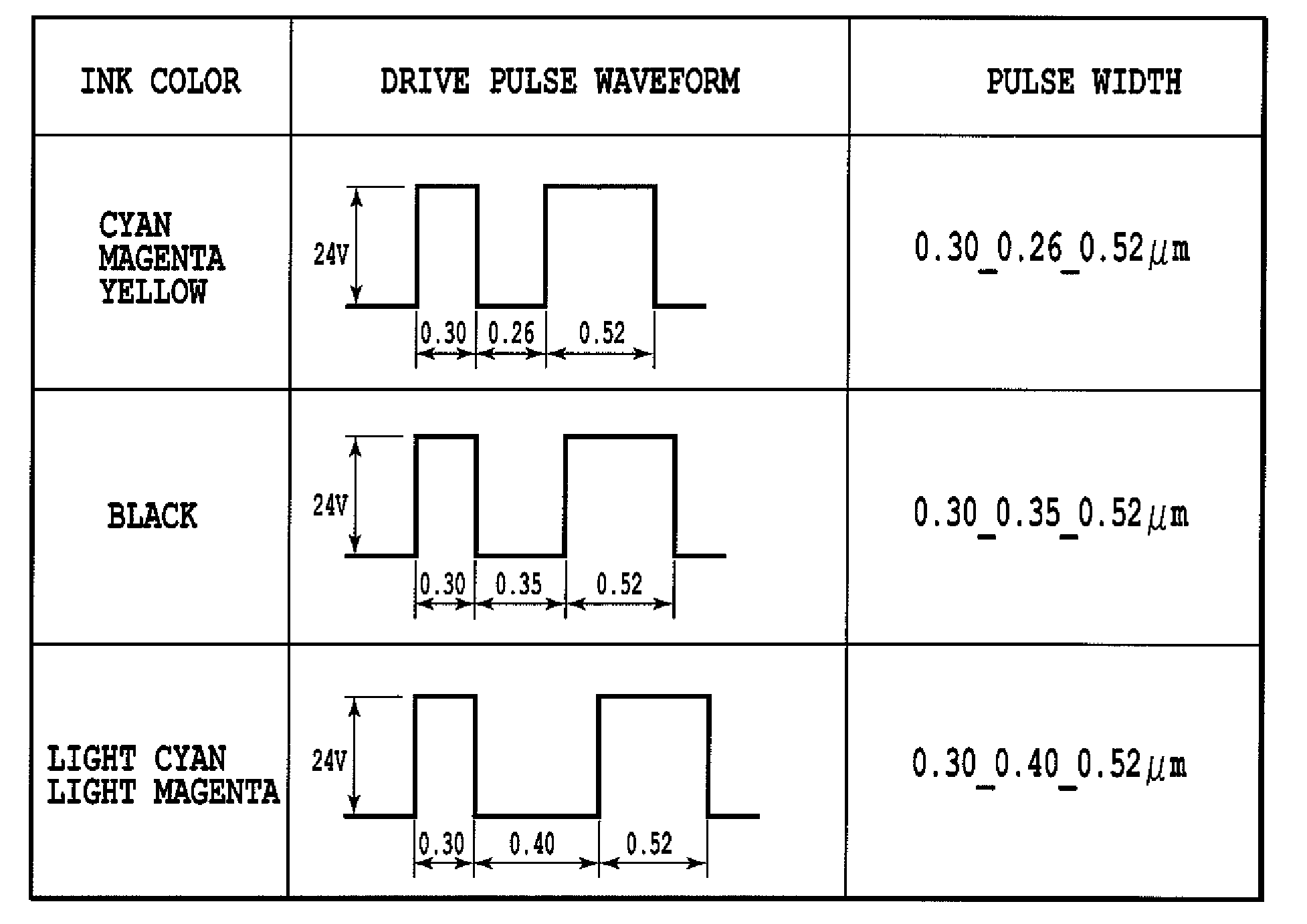
[0080]FIG. 17 is a table showing drive pulse waveforms by ink colors, as applied in this embodiment. In this embodiment, the preheat pulse width P1 is commonly set at 0.30 μs for all colors, but the drive voltage VH, main heat pulse width P3 and interval P2 are set at different values for different colors. More specifically, for cyan, magenta and yellow, the drive voltage VH is set at 20 V, the main heat pulse width P3 at 0.64 μs and the interval P2 at 0.32 μs. For black, the drive voltage VH is set at 22.8 V, the main heat pulse width P3 at 0.58 μs and the interval P2 at 0.38 μs. For light cyan and light magenta, the drive voltage VH is set at 24 V, the main heat pulse width P3 at 0.52 μs and the interval P2 at 0.40 μs.

[0081]Under these settings...


PUM


Abstract

In an ink jet printing apparatus that ejects a plurality of kinds of pigment inks in small droplets, the drive pulse waveform to be applied to each of the heaters is adjusted according to the viscosity of the ink in a way that assures that the lengths of liquid columns ejected are approximately equal among different colors. This enables the dot areas formed on a print medium to be constant among different colors, realizing an image output with excellent color reproducibility, free from variations in image density and tonality.

Description

BACKGROUND OF THE INVENTION[0001]1. Field of the Invention[0002]The present invention relates to an ink jet printing apparatus and an ink jet printing method that form an image on a print medium by ejecting ink droplets (hereinafter referred to as ink) onto the print medium from a print head.[0003]2. Description of the Related Art[0004]The ink jet printing method has many advantages, such as low noise, low running cost and a relative ease with which the apparatus can be reduced in size and upgraded to have a color printing capability. As digital input devices have achieved technical advances and come into wide use in recent years, there are growing calls in an ink jet printing apparatus market for a high-definition, photo-quality image output. To cope with this demand, efforts are being made to reduce the volume of ink droplets ejected from the print head in the ink jet printing apparatus of recent years.[0005]To realize a high image preservation required for a photograph quality, i...

Claims


Application Information

Patent Timeline
Patent Type & Authority Patents(United States)
IPC IPC(8): B41J2/07
CPCB41J2/04571B41J2/04573B41J2/0458B41J2/04588B41J2/04591B41J2/04598B41J2/1752B41J2/17526B41J2/17553B41J2/2056
Inventor MISUMI, YOSHINORI
Owner CANON KK
Why Eureka
Try Eureka