Jet engine nacelle for an aircraft and aircraft comprising such a nacelle

A jet engine and nacelle technology, applied in the direction of machines/engines, air transport, jet propulsion devices, etc., can solve the problems of increasing the complexity and quality of jet nacelles, harmful aerodynamic performance of propulsion devices, etc. The effect of small sound emissions

Inactive Publication Date: 2011-09-21
AIRBUS OPERATIONS (SAS)
View PDF0 Cites 0 Cited by
  • Summary
  • Abstract
  • Description
  • Claims
  • Application Information

AI Technical Summary

Problems solved by technology

[0007] Therefore, installing a conventional variable nozzle system on an airliner risks greatly increasing the complexity and mass of the jet nacelle, detrimental to the aerodynamic performance of the propulsion plant, which is unacceptable

Method used


Image

  • Jet engine nacelle for an aircraft and aircraft comprising such a nacelle
  • Jet engine nacelle for an aircraft and aircraft comprising such a nacelle
  • Jet engine nacelle for an aircraft and aircraft comprising such a nacelle

Examples


Embodiment Construction

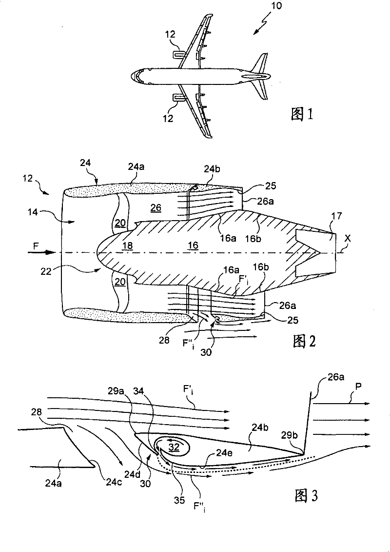
[0043] Such as figure 1 As shown, a commercial aircraft (airline) 10 has a plurality of jet engine nacelles 12 secured to the underside of the aircraft's main wings.

[0044] For example, aircraft 10 is provided with two jet nacelles, each nacelle attached to one of the wings, however, depending on the type of aircraft, multiple nacelles may be attached to the same wing.

[0045] In addition, it may be considered to fix the jet engine nacelle directly on the fuselage, or on both sides of the fuselage, or on the rear upper part of the fuselage.

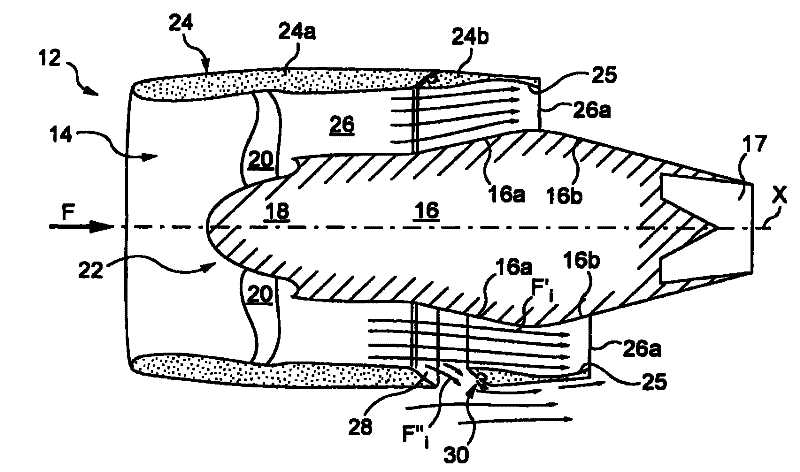
[0046] FIG. 2 schematically shows one of the nacelles 12 according to the invention in longitudinal section.

[0047] A jet engine 14 with longitudinal axis X mounted in the nacelle has a turbine 16 at the inlet, on the upstream side (left in the figure), with a shaft 18 on which is mounted a supercharger 22 of blades 20. The turbines are twin-flow and high bypass ratio turbines (bypass ratio greater than or equal to 5).

[0048] I...


PUM


Abstract

The invention relates to a nacelle (12) for an aircraft high-bypass jet engine, in which a jet engine having a longitudinal axis (X) is mounted, the nacelle including a wall (24) concentrically and atThe invention relates to a nacelle (12) for an aircraft high-bypass jet engine, in which a jet engine having a longitudinal axis (X) is mounted, the nacelle including a wall (24) concentrically and atleast partially surrounding the jet engine and defining with the latter an annular duct (26) for the fluid inner flow, comprising at the downstream end (26a) of said nacelle wall a passage section of least partially surrounding the jet engine and defining with the latter an annular duct (26) for the fluid inner flow, comprising at the downstream end (26a) of said nacelle wall a passage section of the flow outlet, characterised in that the nacelle includes displacement means (42) for displacing on request a portion (24b) of the nacelle wall in order to modify the passage section of the flow outhe flow outlet, characterised in that the nacelle includes displacement means (42) for displacing on request a portion (24b) of the nacelle wall in order to modify the passage section of the flow outlet through which a major portion of the flow (Fi') escapes, said displacement forming in the nacelle wall at least one opening (28; 53) through which a small portion of the flow, called the leak flotlet through which a major portion of the flow (Fi') escapes, said displacement forming in the nacelle wall at least one opening (28; 53) through which a small portion of the flow, called the leak flow (Fi '), naturally escapes, the nacelle further comprising a fluid device (30; ; 54) that uses a fluid for compelling the leak flow to flow along the outer face (24e) of the portion of the nacelle waw (Fi '), naturally escapes, the nacelle further comprising a fluid device (30; ; 54) that uses a fluid for compelling the leak flow to flow along the outer face (24e) of the portion of the nacelle wall located downstream relative to said at least one opening.ll located downstream relative to said at least one opening.

Description

technical field [0001] The invention relates to an aircraft jet nacelle equipped with a variable nozzle system. Background technique [0002] The variable nozzle system was originally developed for military aviation. [0003] These systems can greatly improve the thermodynamic performance of the turbine. [0004] Traditionally, turbines installed on airliners have not been equipped with variable nozzle systems. [0005] In fact, conventional variable nozzle systems lead to very important dimensional constraints, which are directly related to the circumference of the nozzle, whose section must be varied. [0006] However, airliner equipped turbines are characterized by high bypass ratios of essentially 4 to 8, which result in larger nozzle diameters. [0007] It is therefore unacceptable to install a conventional variable nozzle system on an airliner, risking considerably increasing the complexity and mass of the jet nacelle, detrimental to the aerodynamic performance of t...

Claims


Application Information

Patent Timeline
Patent Type & Authority Patents(China)
IPC IPC(8): F02K1/06
CPCY02T50/671F02K3/06F02K1/09F02K1/28Y02T50/60
Inventor G·比兰P·奥贝莱T·叙普利
Owner AIRBUS OPERATIONS (SAS)
Why Eureka
Try Eureka