Eureka AIR delivers breakthrough ideas for toughest innovation challenges, trusted by R&D personnel around the world.

Droplet ejecting apparatus

a technology of ejecting apparatus and droplets, which is applied in the direction of electrical apparatus, piezoelectric/electrostrictive/magnetostrictive devices, printing, etc., can solve the problems of increasing the amount of heat generated by the apparatus, high cost, etc., and achieves the effect of low cost, low cost, and constant speed of ejecting droplets from the nozzl

Active Publication Date: 2007-09-04
BROTHER KOGYO KK
View PDF14 Cites 0 Cited by
  • Summary
  • Abstract
  • Description
  • Claims
  • Application Information

AI Technical Summary

Benefits of technology

[0013]The sum of respective electrostatic capacitances of the plurality of active portions opposed to the pressure chamber is smaller than that of a single active portion that has substantially the same size as that of the pressure chamber and is opposed to the pressure chamber. Therefore, the amount of heat generated by a driver circuit that drives or operates the actuator unit can be reduced. Thus, the driver circuit can enjoy a small size and a low cost. In addition, a heat radiating device that may be employed to radiate the heat generated by the driver circuit can also enjoy a small size.
[0019]According to this mode, the volume of the pressure chamber as a whole corresponding to the active portions can be changed. Thus, a pressure can be effectively applied to the liquid accommodated in the pressure chamber, and a droplet of the liquid can be smoothly ejected from the nozzle.
[0022]According to this mode, an electric voltage that is applied to the actuator unit so as to assure a constant speed of ejection of droplet from the nozzle can be lowered. Therefore, a driver circuit that drives the actuator unit can enjoy a small size and a low cost. For example, the driver circuit may be provided by a low-voltage driver circuit. In addition, since the drive voltage is low, the heat generated by the driver circuit can be reduced and accordingly a heat radiating device that may be employed to radiate the heat can enjoy a small size. Preferably, the above-indicated ratio is not greater than 0.9.

Problems solved by technology

If the electric power consumption of the driver circuit is high, the driver circuit needs to have a large size and accordingly it costs high.
In addition, as the electric power consumption of the driver circuit increases, an amount of heat generated by it increases and accordingly it is needed to employ a heat sink having a large size.

Method used


Image

  • Droplet ejecting apparatus
  • Droplet ejecting apparatus
  • Droplet ejecting apparatus

Examples


examples

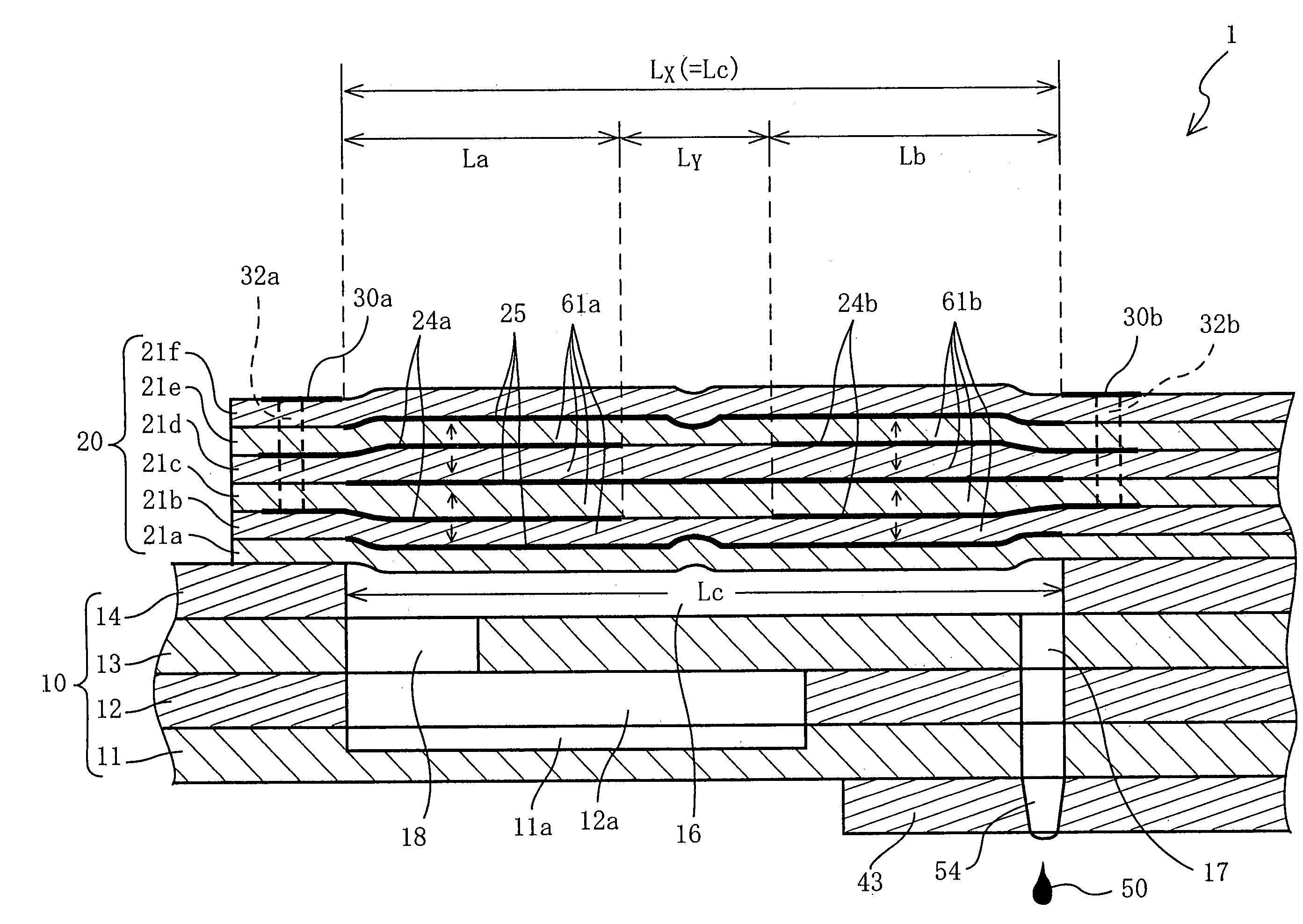
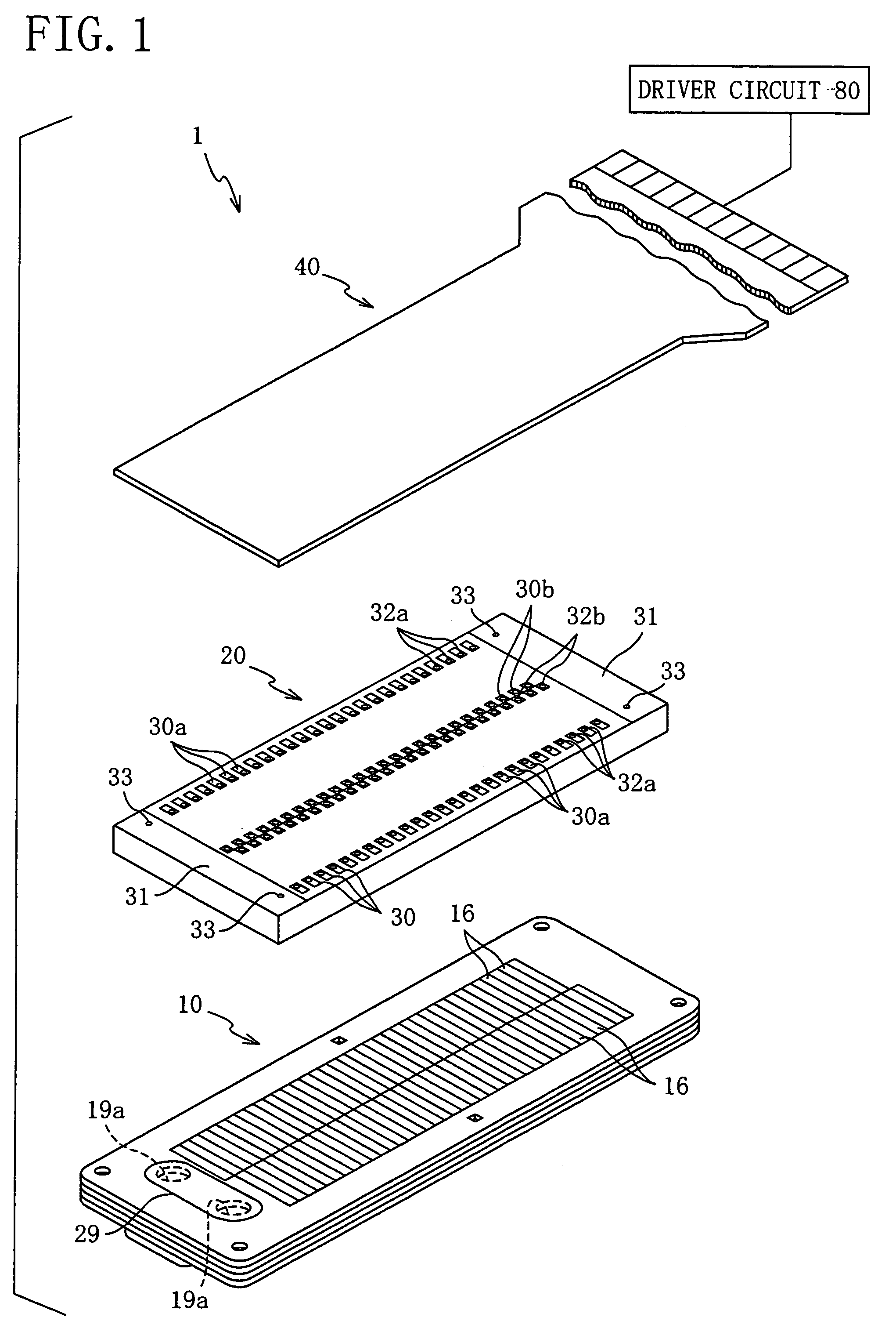
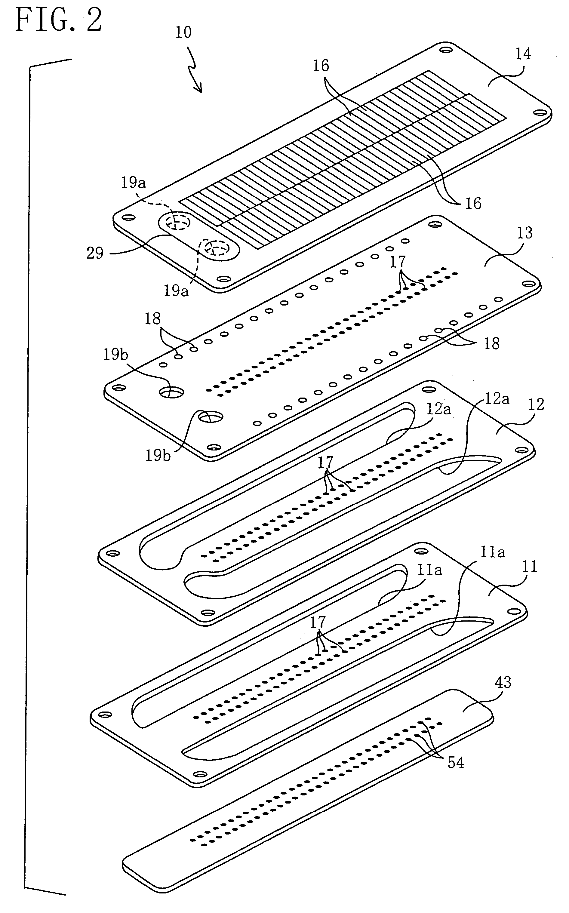
[0068]Various examples of the ink jet printer head 1 according to the present invention, and comparative examples were subjected to an experiment under the conditions that ambient temperature was 25° C. and the speed of ejection of liquid was 9 m / s. In the experiment, an area of a single active portion having the width w and a length equal to the entire length Lc of pressure chamber 16, shown in FIG. 6, was designated as S, and the ratio, (Sa+Sb) / S, of the sum, (Sa+Sb), of respective areas Sa, Sb of the two active portions 61a, 61b to the area S was changed in increments of 0.1 from 0.5 to 1.0 by changing the respective lengths La, Lb of the individual electrodes 24a, 24b and, for each example, an applied voltage and an electrostatic capacitance that were needed to obtain a predetermined change of volume of pressure chamber 16, were measured. The following TABLE shows, for each of the six examples, a relationship between active portion area ratio (Sa+Sb) / S and respective measured va...


PUM


Abstract

An ink jet printer head includes a channel unit and an actuator unit that are bonded to each other. The channel unit has pressure chambers located between a manifold and nozzles. The actuator unit includes piezoelectric sheets, and individual electrodes and common electrodes that are sandwiched by the piezoelectric sheets. Two individual electrodes are paired, and are provided in an area corresponding to each one of the pressure chambers, and cooperate with the common electrodes and the piezoelectric sheets to provide two active portions. When the actuator unit is driven or operated, the two active portions, and respective portions of the piezoelectric sheets that are located between the two active portions are elongated in the direction of thickness of the actuator unit, so that the volume of the each pressure chamber as a whole is decreased. Consequently a droplet of ink is ejected from the nozzle corresponding to the each pressure chamber.

Description

BACKGROUND OF THE INVENTION[0001]1. Field of the Invention[0002]The present invention relates to a droplet ejecting apparatus that changes a volume of a pressure chamber and thereby ejects a droplet from a nozzle.[0003]2. Discussion of Related Art[0004]There is known a droplet ejecting device having a channel unit including a liquid supply manifold that supplies a liquid; a nozzle; and a pressure chamber provided between the liquid supply manifold and the nozzle. The droplet ejecting device changes a volume of the pressure chamber and thereby ejects a droplet of the liquid accommodated in the pressure chamber, from the nozzle. The droplet ejecting device is employed by, e.g., an ink jet printer head, as disclosed by Japanese Patent No. 3,128,857 (FIG. 1) or its corresponding U.S. Pat. No. 5,402,159.[0005]Here, the construction and operation of the droplet ejecting device employed by the above-indicated printer head is described by reference to FIGS. 9 and 10 of the present applicati...

Claims


Application Information

Patent Timeline
Patent Type & Authority Patents(United States)
IPC IPC(8): B41J2/45B41J2/045B41J2/055B41J2/14H01L41/083H01L41/09
CPCB41J2/14209B41J2002/14217B41J2002/14225B41J2002/14338B41J2002/14491
Inventor TAKAHASHI, YOSHIKAZU
Owner BROTHER KOGYO KK
Why Eureka
Eureka Blog
Learn More