AI technical title is built by Patsnap AI team. It summarizes the technical point description of the patent document.
a technology of fibrous pads and printheads, applied in printing and other directions, can solve the problem that a large number of printers are unsuitable for any particular printer
Active Publication Date: 2010-07-13
MEMJET TECH LTD +1
View PDF6 Cites 3 Cited by
Summary
Abstract
Description
Claims
Application Information
AI Technical Summary
This helps you quickly interpret patents by identifying the three key elements:
Problems solved by technology
Method used
Benefits of technology
Benefits of technology
Effectively cleans the printhead nozzle face by mechanically engaging and wicking away contaminants, maintaining cleaning effectiveness over multiple uses and extending the operational life of the wiper pad.
Problems solved by technology
The ordinary worker will appreciate that countless different wiper configurations are possible, of which, the majority will be unsuitable for any particular printer.
Method used
Image
Click on the blue label to locate the original text in one second.
Reading with bidirectional positioning of images and text.
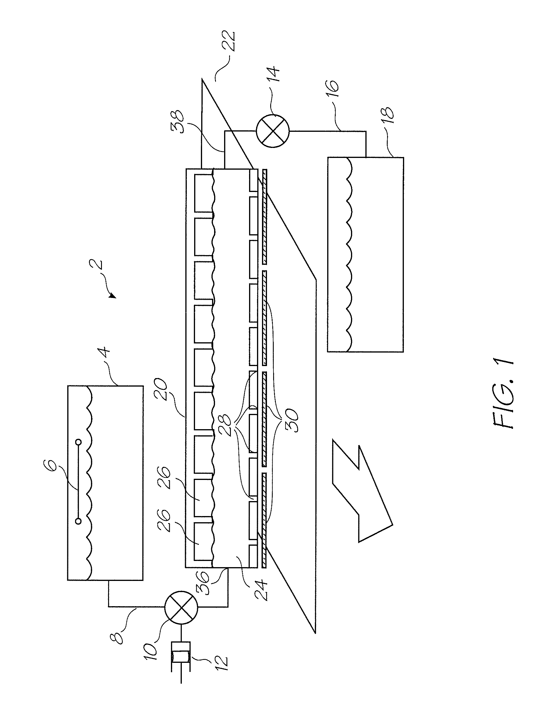
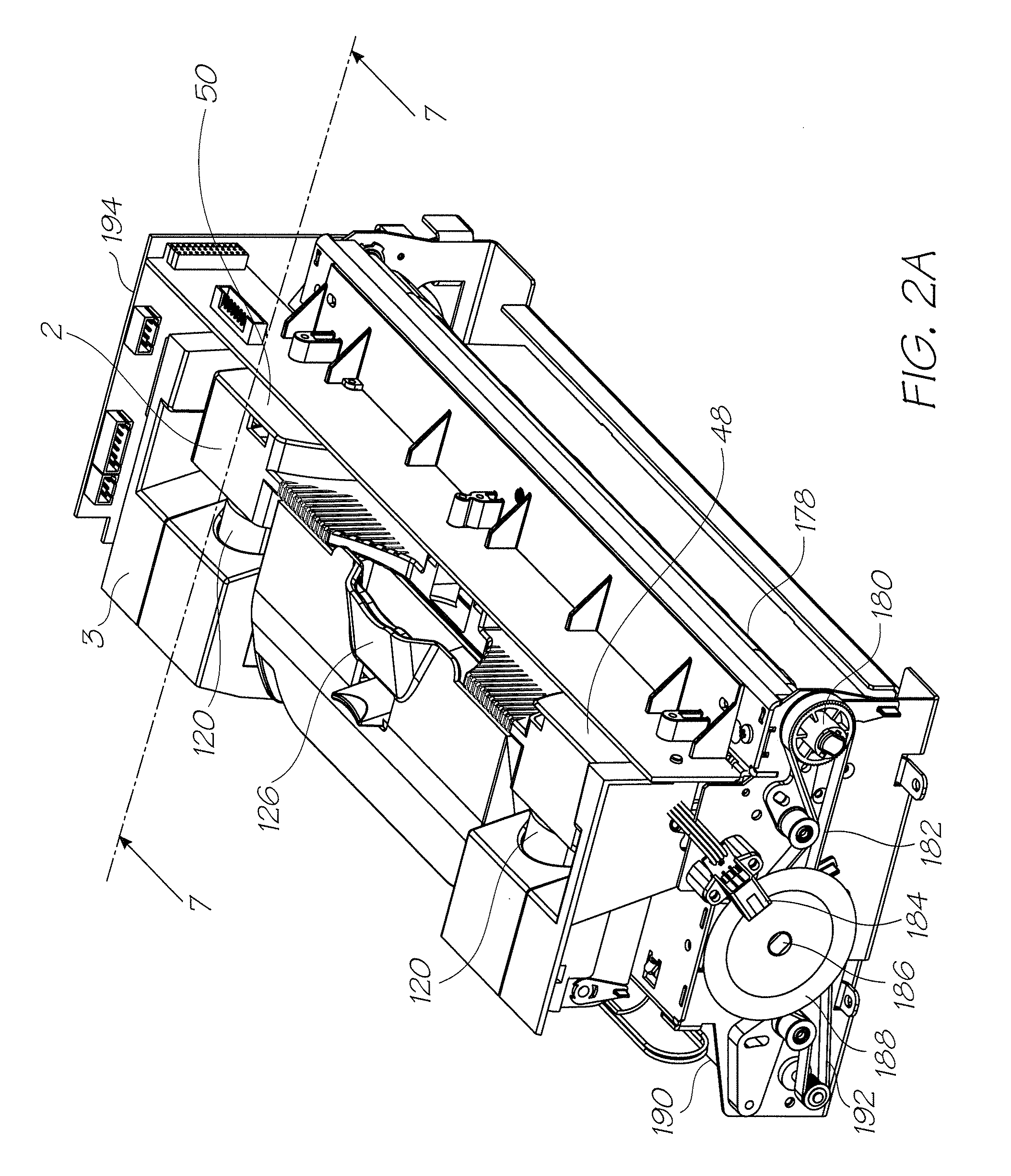
[0067]FIG. 1 is a schematic overview of the fluidic system used by the print engine described in FIGS. 2A and 2B. As previously discussed, the print engine has the key mechanical structures of an inkjet printer. The peripheral structures such as the outer casing, the paperfeed tray, paper collection tray and so on are configured to suit the specific printing requirements of the printer (for example, the photo printer, the network printer or Soho printer). The Applicant's photo printer disclosed in the co-pending application U.S. Ser. No. 11 / 688863 is an example of an inkjet printer using a fluidic system according to FIG. 1. The contents of this disclosure are incorporated herein by reference. The operation of the system and its individual components are described in detail in U.S. Ser. No. 11 / 872719 the contents of which are incorporated herein by reference.
[0068]Briefly, the printer fluidic system has a printhead assembly 2 supplied with ink from an ink tank ...
PUM
Abstract
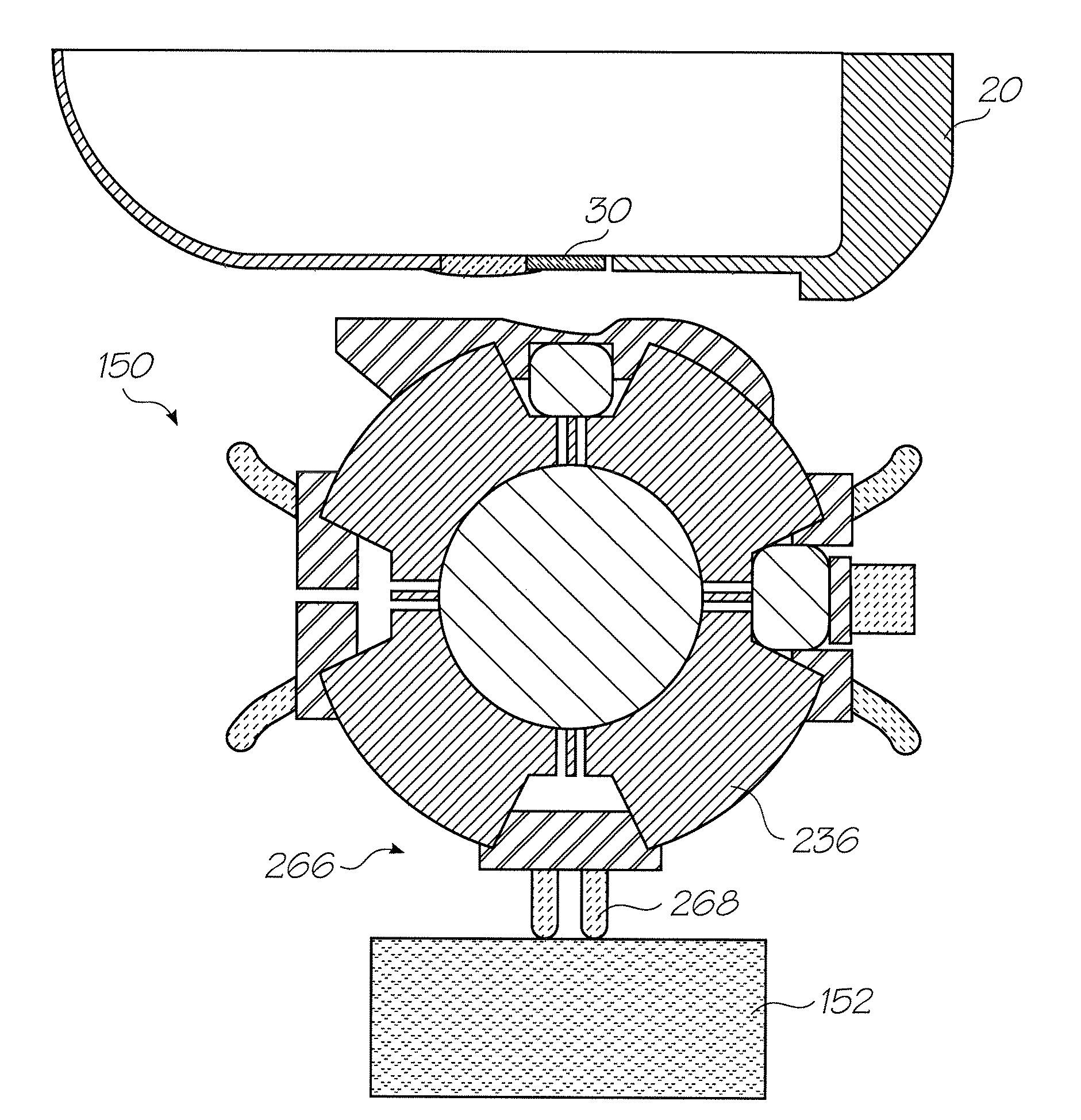
A maintenance facility for an inkjet printer has a printhead with an array of nozzles defined in a nozzle face and media feed assembly for moving sheets of print media along a media feed path extending past the printhead in a media feed direction. The printhead maintenance facility has a wiper member having a fibrous pad for wiping the nozzle face and a maintenance drive for moving the wiper member over the printhead in a direction parallel to the media feed direction. During use, the maintenance drive moves the fibrous pad through the media feed path in order to contact the nozzle face.
Description
FIELD OF THE INVENTION[0001]The present invention relates to be field of printers and in particular pagewidth inkjet printers.CO-PENDING APPLICATIONS[0002]The following applications have been filed by the Applicant simultaneously with the present application:[0003]12 / 014,78812 / 014,76812 / 014,76912 / 014,77012 / 014,77112 / 014,77212 / 014,77312 / 014,77412 / 014,77512 / 014,77612 / 014,77712 / 014,77812 / 014,77912 / 014,78012 / 014,78112 / 014,78212 / 014,78312 / 014,78312 / 014,78512 / 014,78712 / 014,78912 / 014,79012 / 014,79112 / 014,79212 / 014,79312 / 014,79412 / 014,79612 / 014,79812 / 014,80112 / 014,80312 / 014,80412 / 014,80512 / 014,80612 / 014,807The disclosures of these co-pending applications are incorporated herein by reference.CROSS REFERENCES[0004]The following patents or patent applications filed by the applicant or assignee of the present invention are hereby incorporated by cross-reference.[0005]6,276,8506,520,6316,158,9076,539,1806,270,1776,405,0556,628,4306,835,1356,626,5296,981,7697,125,3387,125,3377,136,1867,286,2607,14...
Claims
Application Information
Patent Timeline
Application Date:The date an application was filed.
Publication Date:The date a patent or application was officially published.
First Publication Date:The earliest publication date of a patent with the same application number.
Issue Date:Publication date of the patent grant document.
PCT Entry Date:The Entry date of PCT National Phase.
Estimated Expiry Date:The statutory expiry date of a patent right according to the Patent Law, and it is the longest term of protection that the patent right can achieve without the termination of the patent right due to other reasons(Term extension factor has been taken into account ).
Invalid Date:Actual expiry date is based on effective date or publication date of legal transaction data of invalid patent.
Patent Type & AuthorityPatents(United States)
IPC IPC(8): B41J2/165
CPCB41J2/16538B41J2/16547B41J2/16585
InventorHIBBARD, CHRISTOPHERMACKEY, PAUL IANTSUBONO, MAKOMOSILVERBROOK, KIA

