Telescoping racking system with ramps and platforms

a telescoping racking and platform technology, applied in the direction of couplings, transportation items, manufacturing tools, etc., can solve the problems of deterioration, loss of interchangeability, flexibility, etc., and achieve the effect of enhancing stability and enhancing safety and eas

Inactive Publication Date: 2010-07-13
SPRAGUE DONALD G
View PDF1 Cites 20 Cited by
  • Summary
  • Abstract
  • Description
  • Claims
  • Application Information

AI Technical Summary

Benefits of technology

[0025]In order to enhance safety and ease in such ground-to-bed loading / unloading, the invention employs a rear cross piece that swings clear from the side runners. Thus, the rearmost cross piece securely latches over one side runner, while its other end is swiveled by my coupling to the opposing side runner. Such connections allow the cross piece to be rotated in place for enhanced stability. Or, it may be pivoted out of the way for headroom and equipment clearance during a loading / unloading process.

Problems solved by technology

In either case, however, the prior art structure presents a loss of interchangeability, flexibility and degradation in the strength of the various rack members.
There is little in the way of flexibility and no telescoping involved in such prior art.
In summary, the prior art devices are characterized by a limited range of use and suffer severe limitations for long items.
The length limitation of standard racks means that extra long items in the prior art are haphazardly tied down with ropes or twine.
Such an approach—particularly with do-it-yourselfers—creates extreme safety hazards.
Indeed, many times flexible long items are draped over the windshield area and are tied to the front bumper rearview mirrors or other vehicle parts not intended for such uses.

Method used


Image

  • Telescoping racking system with ramps and platforms
  • Telescoping racking system with ramps and platforms
  • Telescoping racking system with ramps and platforms

Examples


Embodiment Construction

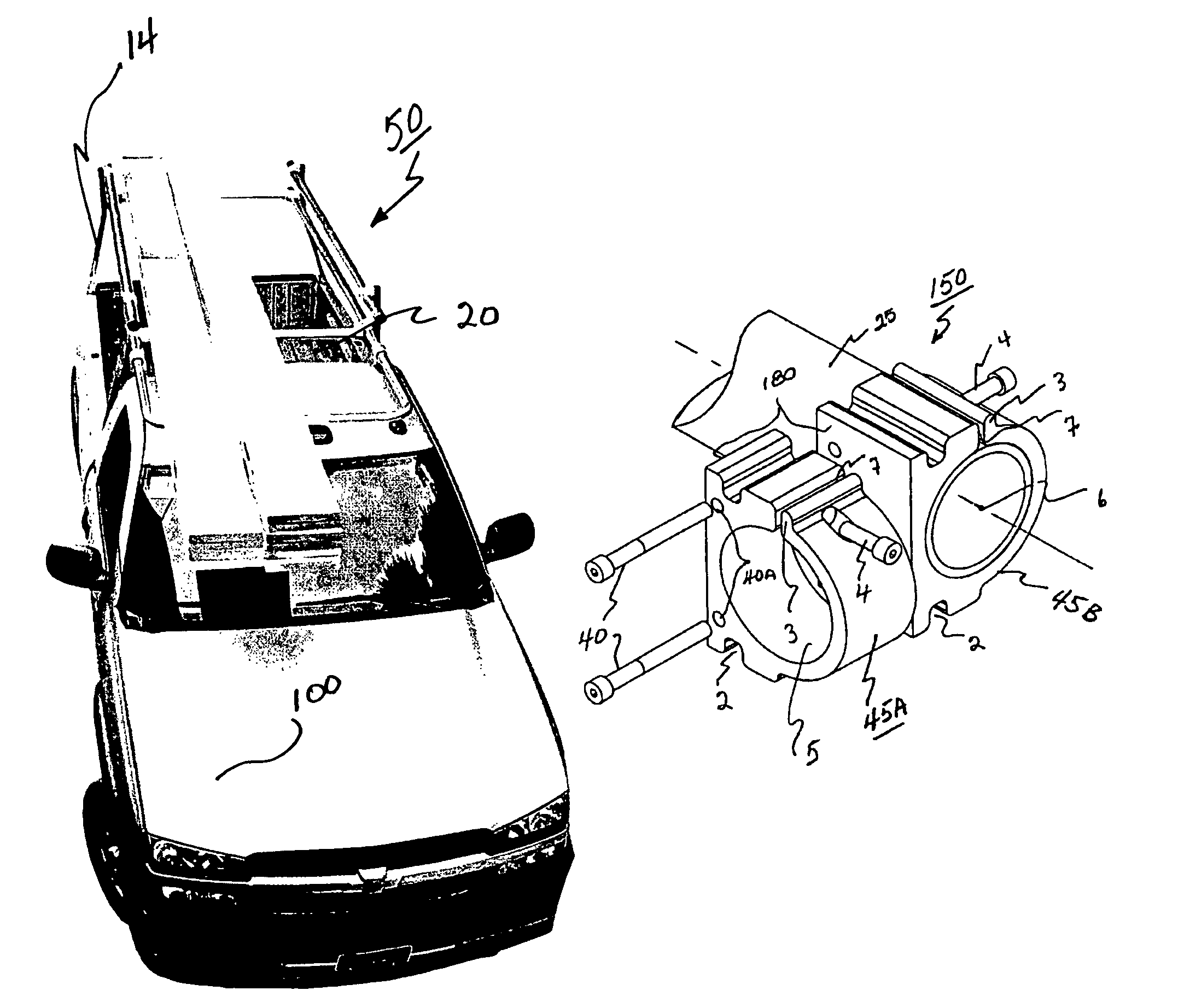
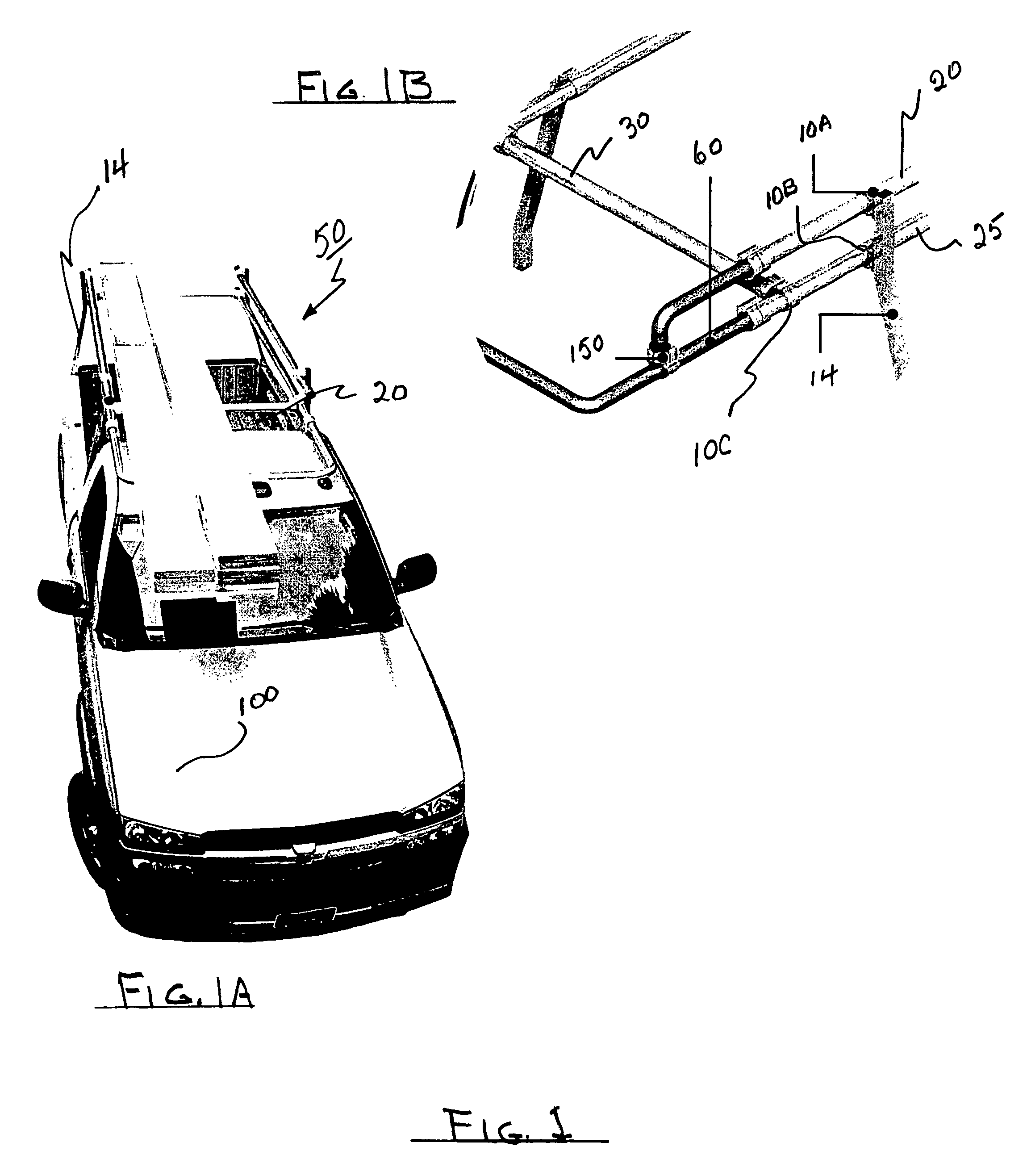
[0056]FIG. 1A depicts a regular sized pickup 100 having one of my inventive racking systems 50 in place on the bed 20. As there depicted, inboard slanting upright posts 14 have been inserted in the pockets of bed 20. (An outward slanting post 15 is shown in FIG. 5 to be described later). The post slant determines the width for my narrower or wider racking systems.

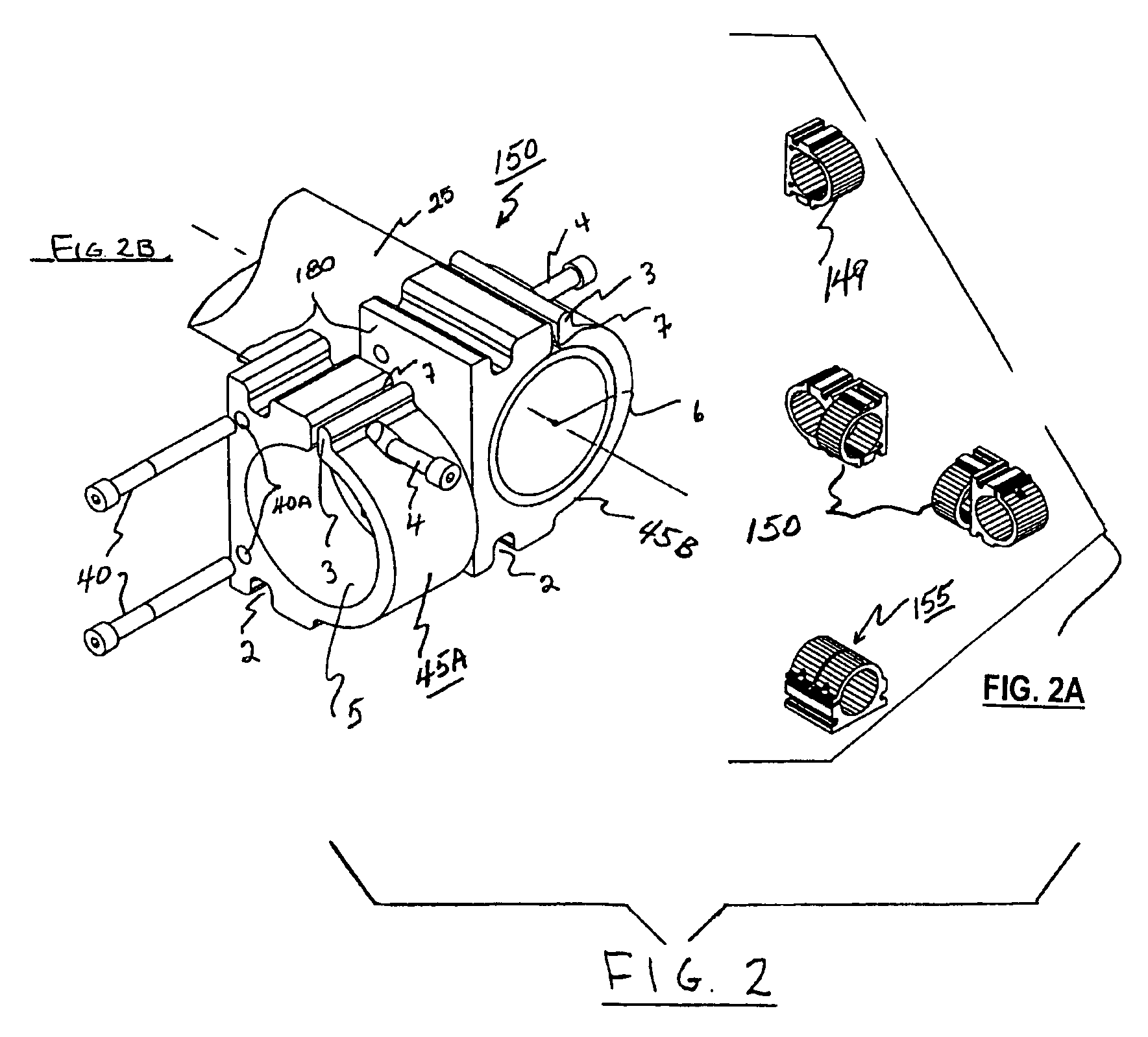
[0057]This FIG. 1 embodiment is a typical example of my novel to racking system selections. It is referred to as a deluxe unit. The rearmost “over the bed part” of the rack 50 may advantageously be fabricated from 2 inch schedule 40 aluminum pipe supported in position by circular pipe openings in a plurality of couplings 10. Each of my rack systems use a number of such couplings 10 that are configured for different functions in accordance with the rack type under consideration.

[0058]As is obvious from a closer study, one will note in FIG. 1 that my coupling 10 is repeated in many locations throughout the rack system 50. Suc...


PUM


Abstract

Long load racking system for vehicles, adjustable runners horizontal and vertical with telescoping members—both single rail, double rail; and trombone shaped; multi-functional, split and corner couplings with accessible transverse to coupling base friction adjustments, ramping ground to bed and bed to elevated locations.

Description

PREVIOUS FILING INFORMATION[0001]On Oct. 22, 2004 the United States Patent Office received a copy of—and assigned Ser. No. 60 / 621,569 to—a Provisional Patent Application (PPA) filed by the same inventor hereof. That PPA is incorporated herein by this reference as though set out here in full. Additionally, the PPA is being supplemented by this Regular Patent Application (RPA). Applicant expressly reserves all rights and privileges flowing from the PPA and its earlier official filing date and contents thereof. This RPA follows, and it is supported by the PPA.[0002]Additionally the invention employs to advantage my novel coupling clamps which are depicted and claimed in my pending application entitled FREE SWINGING PORTABLE CUTTING WORK STATION having Ser. No. 10 / 458,837 filed on Jun. 12, 2003. Particular attention is called to FIG. 7 of that application. That application is incorporated herein as though set forth in full at this point.BACKGROUND OF THE INVENTION[0003]1. Field of the I...

Claims


Application Information

Patent Timeline
Patent Type & Authority Patents(United States)
IPC IPC(8): B60P9/00
CPCB60P3/40B60R9/00Y10T403/7001
Inventor SPRAGUE, DONALD G.
Owner SPRAGUE DONALD G
Why Eureka
Try Eureka