

Piezoelectric ceramic composition and piezoelectric ceramic electronic component
a technology of piezoelectric ceramic and composition, applied in the field of piezoelectric ceramic electronic components, can solve the problems of insufficient increase of piezoelectric d constant, and achieve the effects of improving piezoelectric characteristics, excellent piezoelectric characteristics, and increasing piezoelectric d constan
- Summary
- Abstract
- Description
- Claims
- Application Information
AI Technical Summary
Benefits of technology
Problems solved by technology
Method used
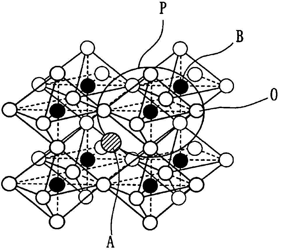
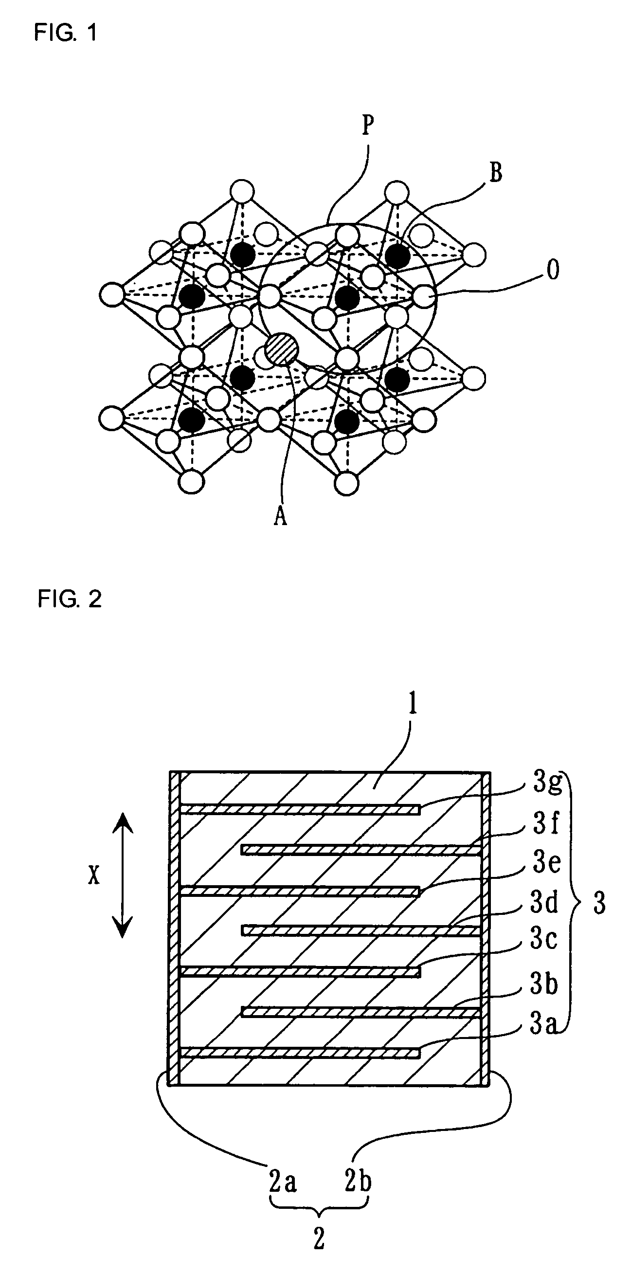
Image

Examples
example 1
[0101]K2CO3, Na2CO3, Nb2O5, Bi2O3, TiO2, ZrO2, SnO2, In2O3, Sc2O3, Yb2O3, Y2O3, Nd2O3, Eu2O3, Gd2O3, Dy2O3, Sm2O3, Ho2O3, Er2O3, Tb4O7 and Lu2O3 were prepared as raw materials for ceramics.
[0102]These raw materials for ceramics were weighed to prepare compositions shown in Table 1. The weighed raw materials were wet-blended in alcohol in a ball mill for 18 hours. Each of the resulting mixtures was dried and calcined at 700 to 1000 degrees C.
[0103]Then, the calcined mixture was roughly ground. The ground mixture and a proper amount of an organic binder were wet-ground in a ball mill for 16 hours and sifted through a 40-mesh sieve to control the particle size.
[0104]Then, the powder having a controlled particle size was pressed at a pressure of 9.8×10⁷ to 1.96×10⁸ Pa into a discoidal compact having a diameter of 10 mm and a thickness of 1.2 mm. The compact was fired at a temperature of 1050 to 1200 degrees C. in the air for two hours to produce a ceramic element.
[0105]A compact was fir...
embodiment 2
[0128]K2CO3, Na2CO3, Li2CO3, Nb2O5, Ta2O5, Sb2O5, Bi2O3, TiO2 and In2O3 were prepared as raw materials for ceramics. These raw materials for ceramics were weighed to prepare the compositions shown in Table 3. Test specimens of sample numbers 31 to 55 were produced by the same method and procedures as in Example 1. The firing temperature range ΔT was also determined as in Example 1.
[0129]The relative dielectric constant ∈r, the electromechanical coupling factor kp, the piezoelectric d33 constant, the piezoelectric d33 constant in a high electric field, and the Curie point Tc were determined by the method and procedures in Example 1.
[0130]Table 3 illustrates the compositions of sample numbers 31 to 55. Table 4 illustrates the measurements and the firing temperature ranges ΔT for sample numbers 31 to 55.
[0131]
TABLE 3Composition:100{(1 − x)(K1−a−bNaaLib)m(Nb1−c−dTacSbd)O3 −Samplex(Na0.5Bi0.5)nTiO3} + In2O3No.xabcdmn310.0050.50000.981320.10.50000.981330.30.50000.981340.50.50000.981 35*0....
embodiment 3
[0152]A predetermined amount of Mn, Ni, Fe, Zn, Cu or Mg was added to the composition of sample number 1. Piezoelectric characteristics and the firing temperature range ΔT were determined.
[0153]More specifically, K2CO3, Na2CO3, Nb2O5, Bi2O3, TiO2, In2O3, MnCO3, NiO, Fe2O3, ZnO, CuO and MgCO3 were prepared as raw materials for ceramics. These raw materials for ceramics were weighed to prepare compositions shown in Table 7. Test specimens of sample numbers 61 to 70 were produced by the same method and procedures as in Example 1. The firing temperature range ΔT was also determined as in Example 1.
[0154]The relative dielectric constant ∈r, the electromechanical coupling factor kp, the piezoelectric d33 constant, the piezoelectric d33 constant in a high electric field, and the Curie point Tc were determined in sample numbers 61 to 70 by the method and procedures in Example 1.
[0155]Table 5 illustrates the compositions of sample numbers 61 to 70, various measurements, and the firing temper...
PUM
| Property | Measurement | Unit |
|---|---|---|
| dielectric constant | aaaaa | aaaaa |
| dielectric constant ∈r | aaaaa | aaaaa |
| dielectric constant ∈r | aaaaa | aaaaa |
Abstract
Description
Claims
Application Information