Arrangement for the suppression of unwanted spectral components in a plasma-based EUV radiation source

a radiation source and unwanted technology, applied in the field of arrangement for the suppression of unwanted spectral components in a plasma-based euv radiation source, can solve the problems of reducing the high exposure accuracy needed in euv lithography, reducing the potential risk of filter membrane destruction, and only reducing the risk of uncontrolled destruction, so as to achieve the effect of simple suppression

Inactive Publication Date: 2010-07-13
USHIO DENKI KK
View PDF20 Cites 3 Cited by
  • Summary
  • Abstract
  • Description
  • Claims
  • Application Information

AI Technical Summary

Benefits of technology

[0013]It is the primary object of the invention to find a novel possibility for the suppression of unwanted spectral components in radiation exiting from a plasma-based EUV radiation source which permits a simple suppression of out-of-band radiation outside the desired EUV range without requiring costly manufacturing and adjustment of diffraction gratings which are prone to contamination.

Problems solved by technology

Of course, UV and DUV spectral components also especially influence the resist optically, which impairs the high exposure accuracy needed in EUV lithography.
However, because of the high power density of the EUV radiation at high repetition frequency, this foil is exposed to very high thermal loads and high-energy particles from the plasma and therefore to the risk of uncontrolled destruction.
A disadvantage of this filter principle consists in that the potential risk of destruction of the filter membrane is only reduced but cannot be eliminated assuming that the filter band is advanced only very slowly or partially at long intervals for cost reasons.
The solutions mentioned above are disadvantageous primarily because of the highly accurate manufacturing requirements and adjusting requirements for the diffraction gratings to achieve the desired filtration and the high susceptibility of the surfaces to contamination, e.g., by carbon deposits.

Method used


Image

  • Arrangement for the suppression of unwanted spectral components in a plasma-based EUV radiation source
  • Arrangement for the suppression of unwanted spectral components in a plasma-based EUV radiation source
  • Arrangement for the suppression of unwanted spectral components in a plasma-based EUV radiation source

Examples


Embodiment Construction

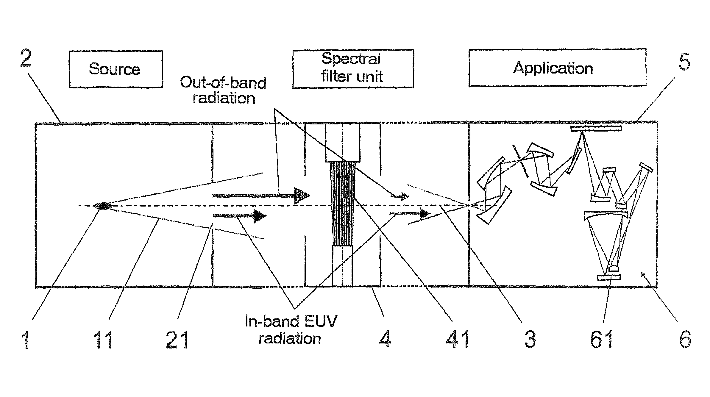
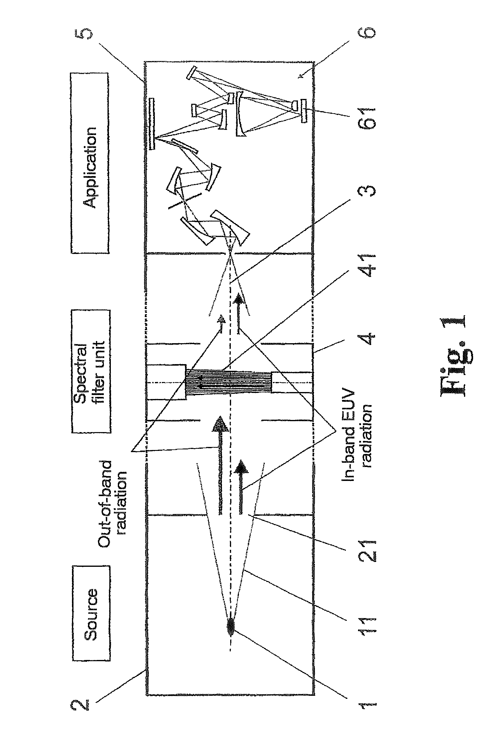
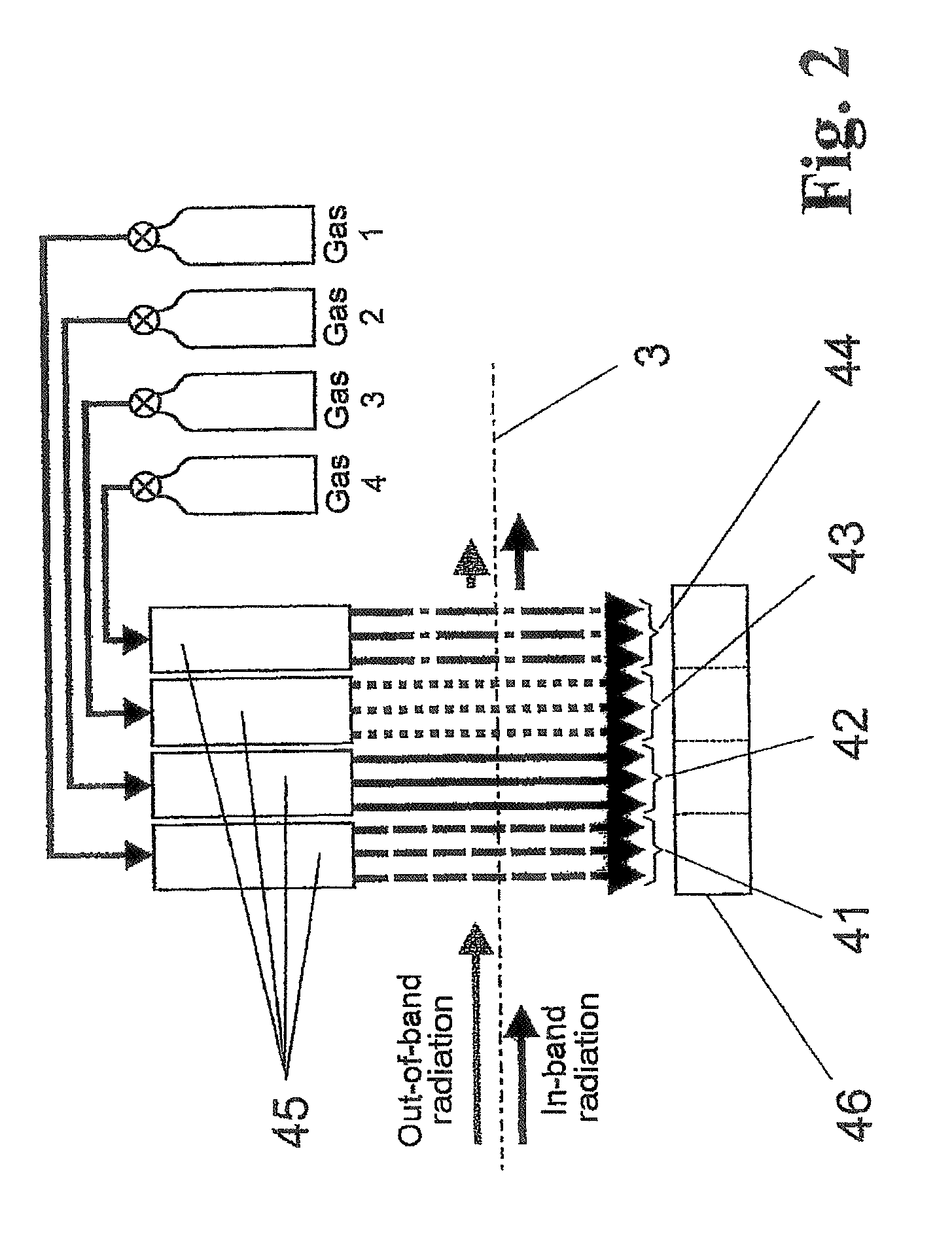
[0043]As is shown in FIG. 1, the basic construction of the arrangement according to the invention comprises the source location of the radiation source in the form of a dense, hot plasma 1 which is generated (in any desired manner) inside a vacuum chamber 2, a light path which, characterized by an optical axis 3, is determined by a bundle of emitted radiation 11 which is coupled out of the vacuum chamber 2 through an outlet opening 21, a spectral filter unit 4 having at least one gas curtain 41 (or a plurality of gas curtains 41 to 44, shown only in FIG. 2), and another vacuum chamber 5 for substantially absorption-free transmission of the wanted EUV radiation (in-band EUV radiation) for the application 6 (e.g., imaging of structures on a wafer 61). For the purpose of generating defined gas curtains 41 (to 44), the spectral filter unit 4 has one or more slit nozzles 45, preferably ultrasonic nozzles, in order to generate gas curtains with high velocity and defined orientation (small...


PUM

PropertyMeasurementUnit
wavelengthsaaaaaaaaaa
thicknessaaaaaaaaaa

Abstract

The invention is directed to an arrangement for the suppression of unwanted spectral components (‘out-of-band’ radiation, as it is called) in a plasma-based radiation source. The object of the invention is to find a novel possibility for the suppression of unwanted spectral components in radiation exiting from a plasma-based EUV radiation source which permits a simple suppression of out-of-band radiation outside the desired EUV range without requiring costly manufacturing and adjustment of diffraction gratings. This object is met according to the invention in that a filter unit is provided between the plasma and an application location of the EUV radiation, which filter unit has at least one gas curtain comprising at least one rapidly flowing gas whose molecules have no absorption maxima for the desired EUV radiation and intensive absorption maxima for other, unwanted wavelengths that are emitted, at least in the IR region. For the purpose of generating the gas curtain, at least one slit nozzle and an efficient gas sink are arranged laterally opposite one another with respect to an optical axis of the beam bundle in order to limit the gas curtain in a spatially defined manner and to remove it again from the vacuum chambers as completely as possible.

Description

CROSS-REFERENCE TO RELATED APPLICATION[0001]This application claims priority of German Application No. 10 2005 048 670.3, filed Oct. 7, 2005, the complete disclosure of which is hereby incorporated by reference.BACKGROUND OF THE INVENTION[0002]a) Field of the Invention[0003]The invention is directed to an arrangement for the suppression of unwanted spectral components (‘out-of-band’ radiation, as it is called) in a plasma-based radiation source, particularly for the suppression of infrared (IR), visible (VIS), ultraviolet (UV) and / or deep ultraviolet (DUV) spectral components which are typically generated along with short-wavelength radiation, e.g. X-radiation to EUV radiation.[0004]b) Description of the Related Art[0005]For applications in semiconductor lithography, semiconductor wafers require increasingly higher EUV outputs to be generated by plasma-based radiation sources. However, the output of DUV, UV, VIS and IR wavelengths which is emitted by the plasma in addition to the de...

Claims


Application Information

Patent Timeline
Patent Type & Authority Patents(United States)
IPC IPC(8): H01L21/027G21K3/00G03F7/20
CPCB82Y10/00G03F7/70033G03F7/70191G03F7/70575G03F7/70908G03F7/70916G03F7/70933G03F7/70991G21K1/10H05G2/001
Inventor DE BRUIJN, RENETRAN, CHINH DUCMADER, BJOERNBRUDERMANN, JESKOKLEINSCHMIDT, JUERGEN
Owner USHIO DENKI KK
Why Eureka
Try Eureka