Plasma display panel

a technology of display panel and plasma, which is applied in the direction of gas exhaustion means, gas-filled discharge tubes, gas discharge vessels/containers, etc., can solve the problems of deterioration of panel characteristics, difficulty in exhausting impurity gases, and reduction of brightness and voltage variations, so as to prevent a reduction of the aperture ratio of cells, the effect of sufficient ventilation conductance and high brightness

Inactive Publication Date: 2010-07-13
HITACHI CONSUMER ELECTRONICS CORP
View PDF16 Cites 0 Cited by
  • Summary
  • Abstract
  • Description
  • Claims
  • Application Information

AI Technical Summary

Benefits of technology

[0012]The present invention, which has been made to solve the above-mentioned problems, provides a structure in which, at a vent passage formed by dividing each barrier rib in the row direction into two portions in the column direction, a raised portion, which is lower than each barrier rib in the row direction and connects the two portions of the barrier rib in the row direction that have been divided, is formed so that it becomes possible to prevent the barrier ribs in the row direction from tilting toward the cell side at the time of firing the barrier ribs.
[0014]In accordance with the present invention, it becomes possible to prevent a reduction in the aperture ratio of the cells with a sufficient ventilation conductance property being maintained, and consequently to achieve a panel having high brightness and improve the stability in the phosphor applying process.

Problems solved by technology

In this case, the PDP having the closed-type structure of barrier ribs has a smaller ventilation conductance in the panel in comparison with the PDP having the linear structure of barrier ribs, resulting in difficulty in exhausting the impurity gases.
When the removal of the impurity gases is insufficient, the characteristics of the panel deteriorate.
More specifically, there is a reduction in the brightness and variations in the voltage due to degradation of the phosphor, and display irregularities in the panel tend to be caused.
For this reason, the aperture ratio (area of cell region / area of display region) becomes smaller, resulting in a problem of low display brightness.
Here, a phosphor paste is applied to the inside of each cell, and by firing the phosphor paste, the phosphor layer is formed; however, the reduction in the aperture ratio tends to impair the stability in the phosphor paste applying process.

Method used


Image

  • Plasma display panel
  • Plasma display panel
  • Plasma display panel

Examples


first embodiment

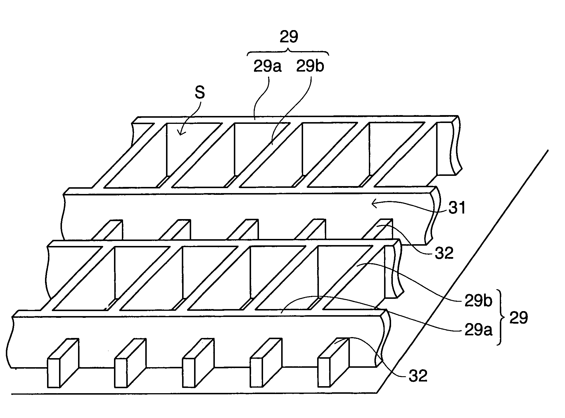
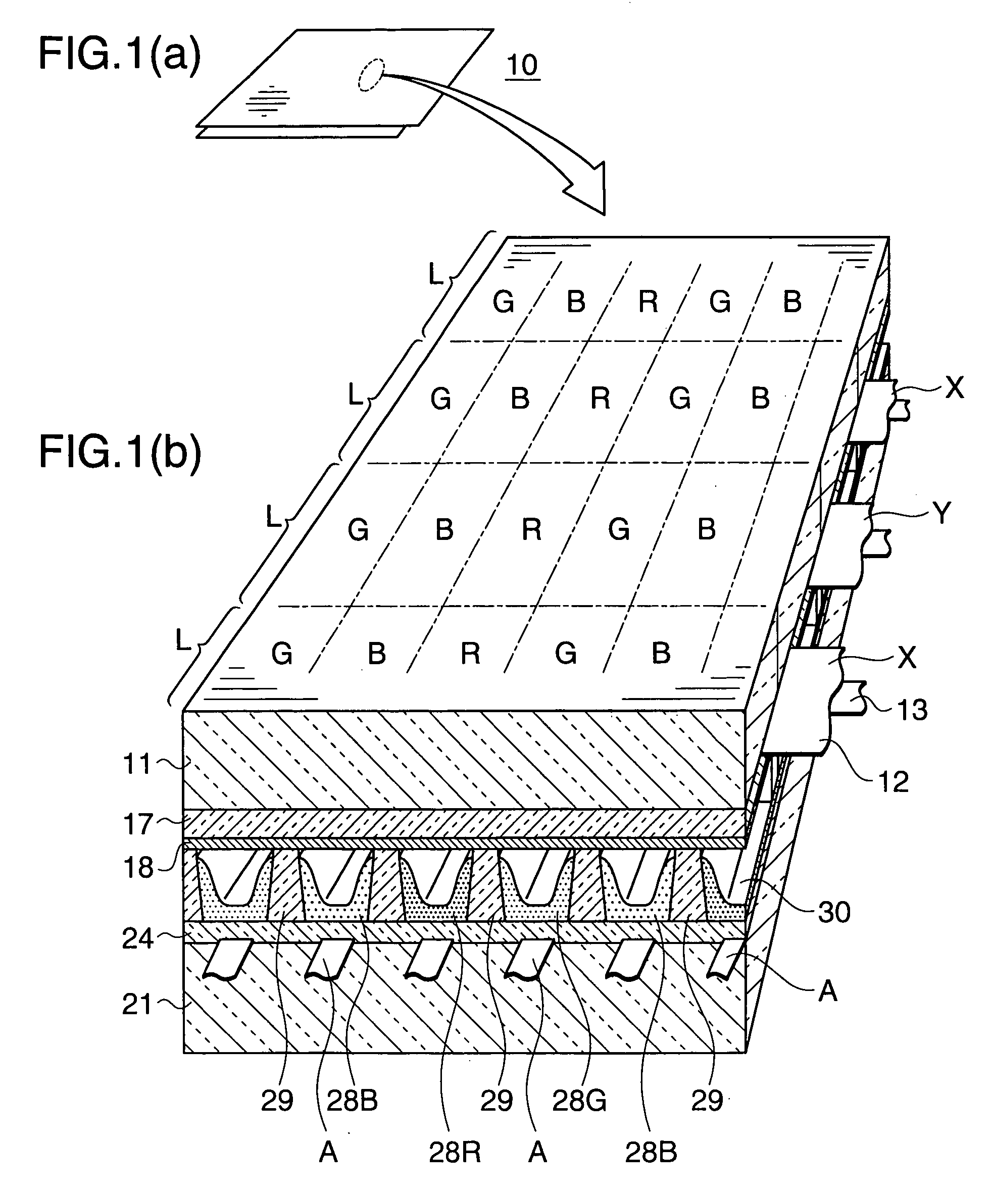
[0038]FIG. 2 is a perspective view that shows the barrier ribs of a PDP in accordance with the present invention.

[0039]As shown in this figure, in the PDP of the present embodiment, a discharge space, formed between the substrate on the front face side and the substrate on the back face side, is divided by barrier ribs 29. The barrier ribs 29 are formed on the substrate on the back face side.

[0040]The barrier ribs 29 include lateral barrier ribs 29a that extend in the row direction, and longitudinal barrier ribs 29b that extend in the column direction, a discharge space is divided by the lateral barrier ribs 29a and the longitudinal barrier ribs 29b into respective cells S. In a plan view, each cell S has a rectangular shape. Each barrier rib 29a in the row direction is divided into two portions in the column direction, and a groove at the divided position forms a vent passage 31.

[0041]FIG. 3(a) is an explanatory view that shows a state in which the barrier ribs of the first embodim...

second embodiment

[0048]FIG. 4(a) is an explanatory diagram that shows a state in which barrier ribs in accordance with the present invention are viewed from above, and FIG. 4(b) is an explanatory diagram that shows a cross section taken along IV-IV in FIG. 4(a).

[0049]In the present embodiment, the shape of the barrier ribs 29 is the same as that of the first embodiment; however, raised portions formed in a vent passage 31 are prepared as a raised portion 33 having a continuous belt shape along the lateral barrier ribs 29a. Even when such a belt-shaped raised portion 33 is used, the same effects as those of the first embodiment can be obtained.

[0050]As described above, in accordance with the present invention, a PDP is provided with barrier ribs including lateral barrier ribs extending in the row direction and longitudinal barrier ribs extending in the column direction, with a vent passage being formed at a position where each lateral barrier rib is divided into two portions in the column direction, ...


PUM


Abstract

A plasma display panel includes a pair of substrates forming a discharge space between the substrates, and lateral barrier ribs extending in a row direction and longitudinal barrier ribs extending in a column direction that divide the discharge space into cells. Each lateral barrier rib is divided into two portions in the column direction such that a vent passage is formed in the divided portion. In the plasma display panel, raised portions, which are lower than the lateral barrier ribs and connect the lateral barrier ribs divided into the two portions with each other, are formed in the vent passage.

Description

CROSS-REFERENCE TO RELATED APPLICATION[0001]This application is related to Japanese application No. 2006-268256 filed on Sep. 29, 2006 whose priority is claimed under 35 USC §119, the disclosure of which is incorporated by reference in its entirety.BACKGROUND OF THE INVENTION[0002]1. Field of the Invention[0003]This invention relates to a plasma display panel (hereinafter, referred to as “PDP”), and more particularly, relates to a PDP in which barrier ribs of a closed type that divide a discharge space into respective cells are disposed between a pair of substrates forming a panel.[0004]2. Description of the Related Art[0005]An AC drive three-electrode face discharge type PDP has been known as a conventional PDP. This PDP is manufactured by aligning a front-side substrate on which desired constituent elements such as electrodes, dielectric layers, phosphor layers and barrier ribs are formed and a back-side substrate face to face with each other and by sealing the peripheral portion ...

Claims


Application Information

Patent Timeline
Patent Type & Authority Patents(United States)
IPC IPC(8): H01J17/00H01J11/22H01J11/34H01J11/36
CPCH01J11/12H01J11/36H01J11/54H01J2211/361
Inventor TAKAGI, KAZUSHIGESEO, YOSHIHOINOUE, HAJIMEKOSAKA, TADAYOSHISAKITA, KOICHI
Owner HITACHI CONSUMER ELECTRONICS CORP
Why Eureka
Try Eureka