
Apparatus for power amplification based on envelope elimination and restoration (EER) and push-pull switching

a technology of power amplifier and push-pull switch, which is applied in the direction of push-pull amplifier, phase splitter, gain control, etc., can solve the problems of not being able to develop a pa that meets all high efficiency, power requirements, and a great deal of weight of pa, so as to enhance the efficiency of the power amplifier.

Inactive Publication Date: 2010-07-13
SAMSUNG ELECTRONICS CO LTD
View PDF3 Cites 74 Cited by
  • Summary
  • Abstract
  • Description
  • Claims
  • Application Information

AI Technical Summary

Benefits of technology

[0009]An aspect of the present invention is to address at least the above mentioned problems and / or disadvantages and to provide at least the advantages described below. Accordingly, an aspect of the present invention is to provide an apparatus for enhancing efficiency of a power amplifier (PA) based on envelope elimination and restoration (EER).
[0010]Another aspect of the present invention is to provide an apparatus for enhancing efficiency of an envelope amplifier in a PA based on EER.

Problems solved by technology

In terms of cost, the PA is given a great deal of weight.
Yet, it is not easy to develop a PA satisfying all of high efficiency, broad band, and high power requirements.
However, it is hard to enhance both the efficiency and the band characteristic because of the high-level implementation.
However, as the switching frequency gets higher, loss also increases, thereby rendering the buck converter as being unsuitable for high frequency operations.
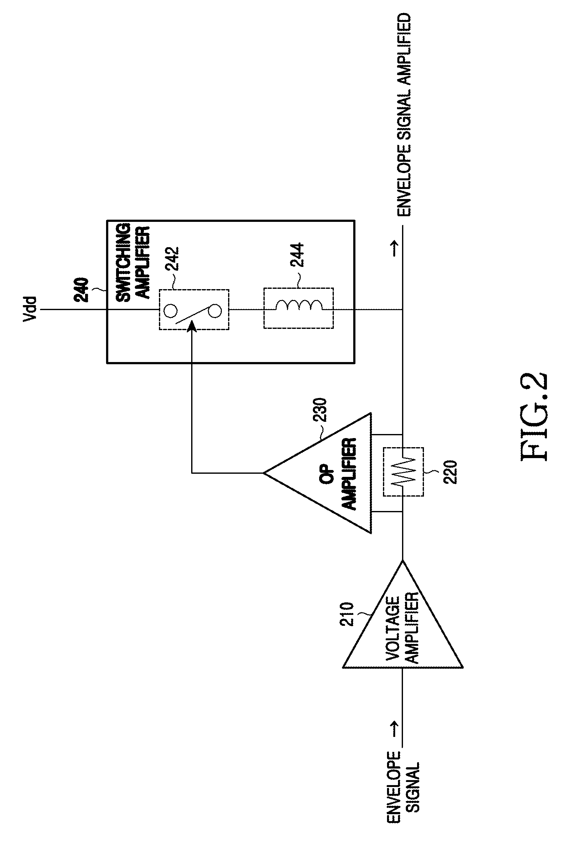
However, as the switching frequency of the signal fed to the switching amplifier 240 gets higher, the loss increases, thereby degrading the total efficiency instead.

Method used


Image

  • Apparatus for power amplification based on envelope elimination and restoration (EER) and push-pull switching
  • Apparatus for power amplification based on envelope elimination and restoration (EER) and push-pull switching
  • Apparatus for power amplification based on envelope elimination and restoration (EER) and push-pull switching

Examples


Embodiment Construction

[0023]The following description with reference to the accompanying drawings is provided to assist in a comprehensive understanding of exemplary embodiments of the present invention as defined by the claims and their equivalents. It includes various details to assist in that understanding but these are to be regarded as merely exemplary. Accordingly, those of ordinary skill in the art will recognize that various changes and modifications of the embodiments described herein can be made without departing from the scope and spirit of the invention.

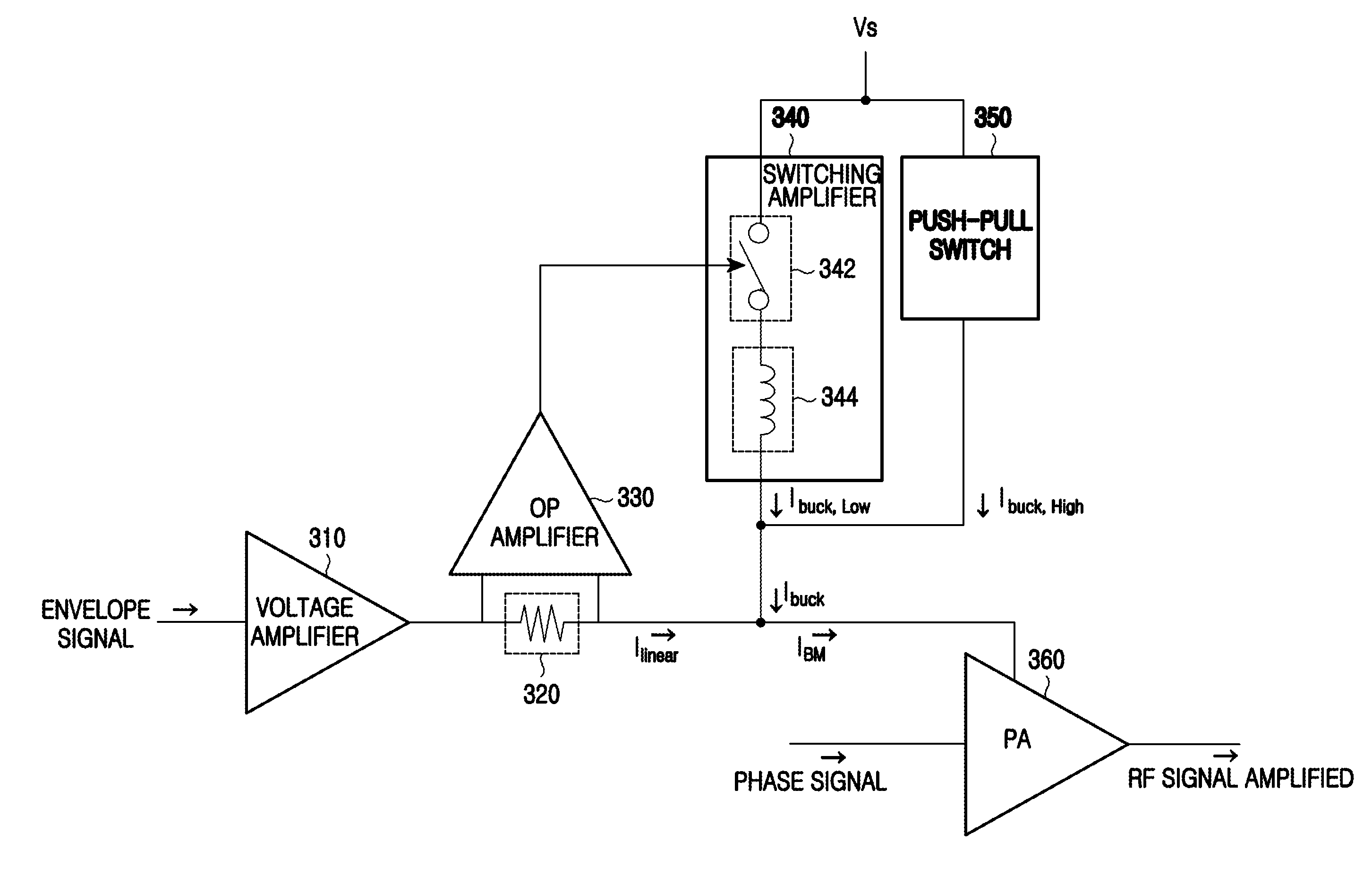
[0024]FIG. 3 illustrates a power amplifying apparatus based on envelope elimination and restoration (EER) according to an exemplary embodiment of the present invention. The power amplifying apparatus of FIG. 3 includes a voltage amplifier 310, a resistor 320, an operational (OP) amplifier 330, a switching amplifier 340, a push-pull switch 350, and a power amplifier (PA) 360.

[0025]The voltage amplifier 310 amplifies a high frequency component o...


PUM


Abstract

A power amplifying apparatus based on envelope elimination and restoration (EER) includes a voltage amplifier to amplify a high frequency component of an envelope signal, a switching amplifier to generate a low frequency component signal of a drain bias based on a first pulse width modulation (PWM) signal that corresponds to a low frequency component of the envelope signal, and a push-pull switch, connected to the switching amplifier in parallel, to add a high frequency component signal to an output of the switching amplifier by pushing or pulling current to or from the output of the switching amplifier.

Description

PRIORITY[0001]This application claims the benefit under 35 U.S.C. §119(a) to a Korean patent application filed in Korean on Dec. 24, 2007 and assigned Application No. 10-2007-0136223, the entire disclosure of which is hereby incorporated by reference.BACKGROUND OF THE INVENTION[0002]1. Field of the Invention[0003]The present invention relates generally to a power amplifier. More particularly, the present invention relates to a power amplifying apparatus based on envelope elimination and restoration (EER) using push-pull switching.[0004]2. Description of the Related Art[0005]A power amplifier (PA) is generally used to amplify a transmit signal in a wireless communication system. In terms of cost, the PA is given a great deal of weight. Many developers of wireless communication systems are making efforts to develop a PA with high efficiency. Yet, it is not easy to develop a PA satisfying all of high efficiency, broad band, and high power requirements. To raise the efficiency of the PA...

Claims


Application Information

Patent Timeline
Patent Type & Authority Patents(United States)
IPC IPC(8): H03F3/04
CPCH03F1/0227H03F3/217H03F3/24H02M3/158H03F2200/102H03F2200/351H03F2200/504H03F1/32H03F3/20
Inventor SUN, KAE-OH
Owner SAMSUNG ELECTRONICS CO LTD
Learn More