
Radio integrated circuit and radio communication method

a radio communication and integrated circuit technology, applied in the field of large-scale radio integrated circuits, can solve the problem that the system configuration cannot maintain the bi-band of the beacon interval, and achieve the effect of reducing the shift of the beacon interval

Inactive Publication Date: 2010-07-13
LAPIS SEMICON CO LTD
View PDF14 Cites 3 Cited by
  • Summary
  • Abstract
  • Description
  • Claims
  • Application Information

AI Technical Summary

Benefits of technology

The present invention provides a PHY-equipped radio LSI and a radio communication method that can solve the problems of the conventional PHY-equipped radio LSI and the radio communication method. The invention includes a switching circuit that can maintain the beacon interval without fail and a clear circuit that can switch to the output side of the third latch circuit to allow for subsequent data transmission. The invention also includes a storage part for storing demodulated data and a transfer part for controlling the transfer of data between the MAC part and the storage part. The technical effects of the invention include ensuring consistent beacon interval and maintaining data transmission with a consistent beacon interval.

Problems solved by technology

However, the conventional PHY-equipped radio LSI 10B and radio communication method has the following problems.
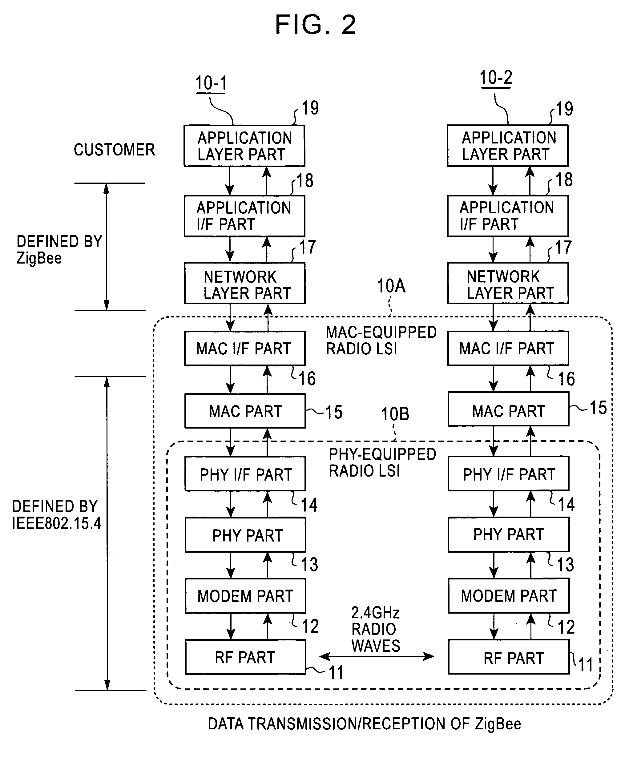
For this reason, if the external MAC part 15 recognizes a determined transfer of transmission data and transmits the transmission data to the PHY I / F part 14 in the radio LSI 10B, a problem arises in that the beacon interval BI cannot be maintained by the system configuration due to not only a time loss caused by PHY / IF (serial transfer) but also a dependence on the clock frequency for serial transfer.

Method used


Image

  • Radio integrated circuit and radio communication method
  • Radio integrated circuit and radio communication method
  • Radio integrated circuit and radio communication method

Examples


first embodiment

Configuration of First Embodiment

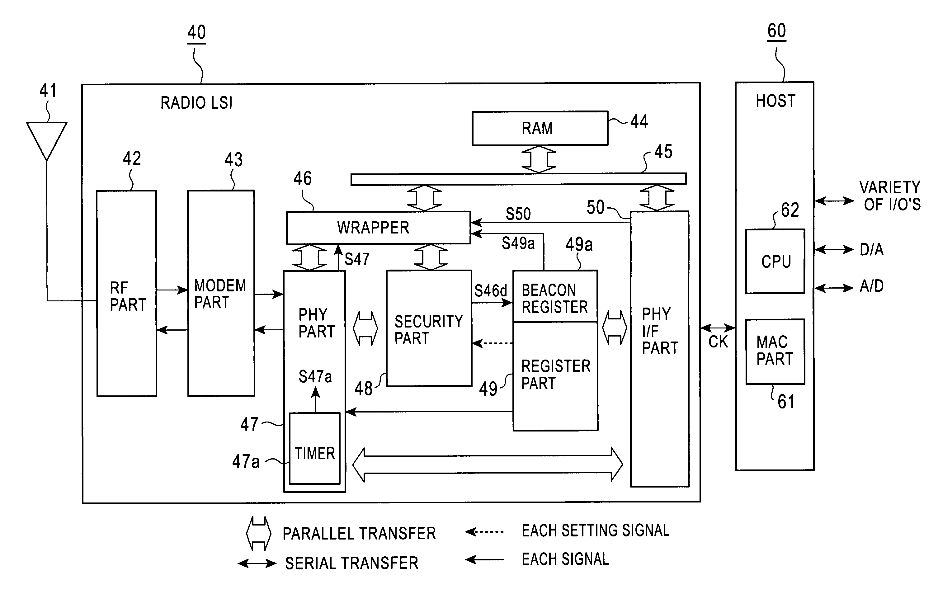
[0052]FIGS. 5A, 5B are diagrams generally showing the configuration of a PHY-equipped radio LSI according to a first embodiment of the present invention, where FIG. 5A is a general functional block diagram, and FIG. 5B is a diagram showing the configuration of a switching circuit provided in a wrapper in FIG. 5A.

[0053]The PHY-equipped radio LSI 40 shown in FIG. 5A is a chip for serially communicating signals with a host 60 through SCI or the like, and comprises an RF part 42 connected to an antenna 41. The RF part 42 is a transceiver comprising an analog radio circuit for performing transmission / reception through the antenna 41 at RF 2.5 GHz defined by the PHY 1 of IEEE 802.15.4, shown in FIG. 1. A modem part 43 is connected to the RF part 42 through a serial transfer signal line. The modem part 43 modulates or demodulates data with the PHY 1 in accordance with a modulation / demodulation circuit specifications defined by the PHY 1 of IEEE 802.15.4.

[00...


PUM


Abstract

A PHY-equipped radio LSI and a radio communication method capable of transmitting data without fail while maintaining a beacon interval. Using a selector which is switched by a beacon transmission signal output from a beacon register, a data transmission request signal is switched for transmitting data from a RAM to a PHY part, and a transfer is started when this signal goes to “1.” In this way, for transmitting beacon data, the beacon data has been previously transferred to the RAM, and the beacon data is transmitted at the time of beacon transmission interval with the PHY part remaining in a transmission state, so that the beacon interval can be maintained. In addition, it is possible to prevent a failure in the transmission of transfer data due to the state of the PHY part.

Description

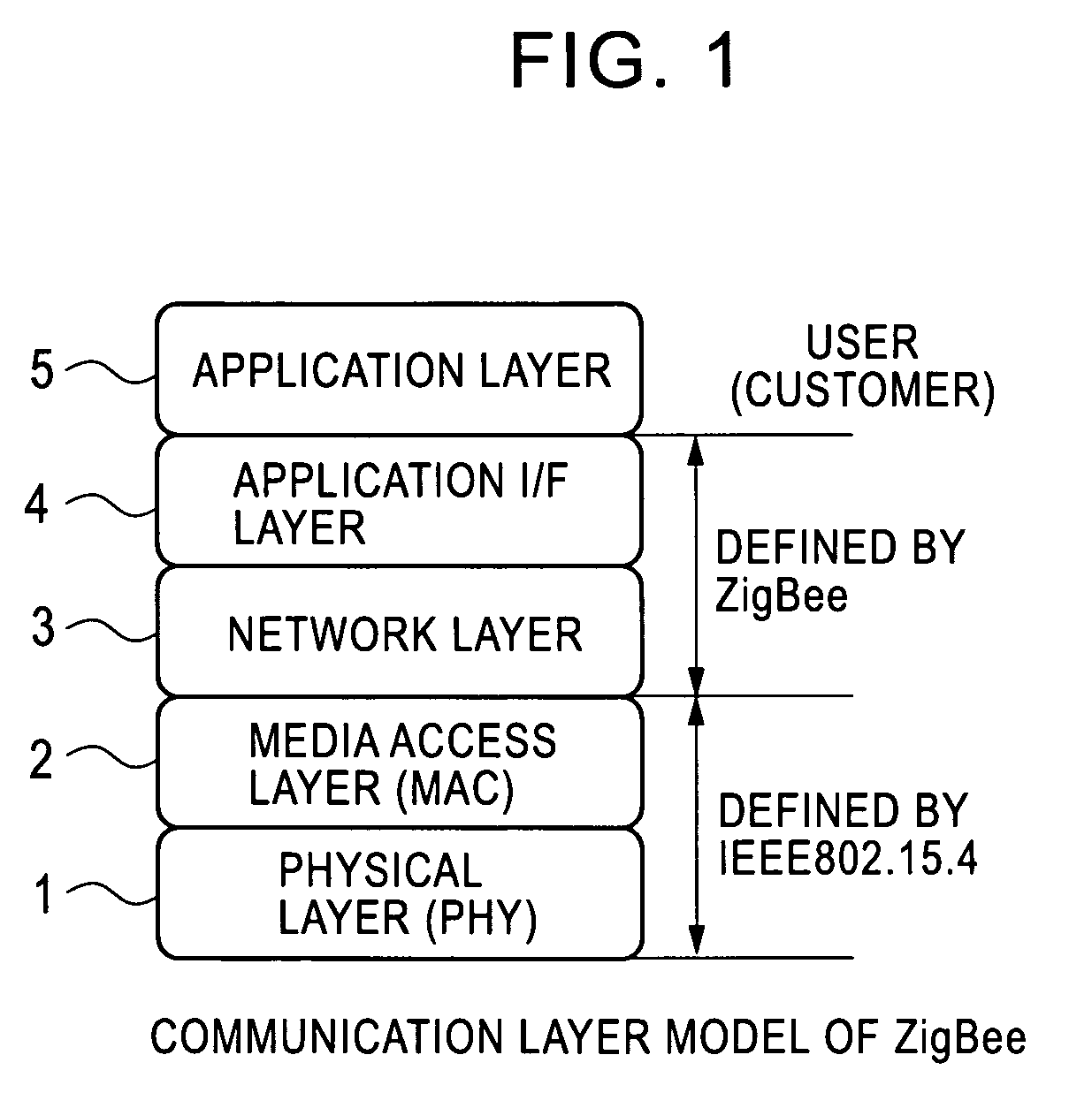
BACKGROUND OF THE INVENTION[0001]1. Field of the Invention[0002]The present invention relates to a large-scale radio integrated circuit (hereinafter called the “radio LSI”) which includes an interface (hereinafter called the “I / F”), conforming to IEEE (the Institute of Electric and Electronic Engineers) 802.15.4, with a physical layer (hereinafter called the “PHY”) and a data link layer including a media access control layer (hereinafter called the “MAC”) higher than the physical layer, and employs ZigBee (a trademark of ZigBee Alliance), which is one of near field radio communication standards included in radio communication standards, which divides a 2.4-GHz frequency band, the same as a radio LAN (Local Area Network) standard IEEE 802.11b, into 16 channels for utilization, and to a radio communication method, particularly, a transmission data control therefor.[0003]2. Description of the Related Art[0004]Conventional radio LSI's employing ZigBee and radio communication methods hav...

Claims


Application Information

Patent Timeline
Patent Type & Authority Patents(United States)
IPC IPC(8): H04J3/22
CPCH04L63/0428H04L12/28
Inventor KAI, ATSUHIRO
Owner LAPIS SEMICON CO LTD
Learn More