Storage device and storing method

a storage device and a technology for storing devices, applied in the field of storage devices and storing methods, can solve the problems of prolonging the lifetime, unable to eliminate the lifetime, and impossible to eliminate the lifetim

Inactive Publication Date: 2010-07-13
HITACHI LTD
View PDF1 Cites 218 Cited by
  • Summary
  • Abstract
  • Description
  • Claims
  • Application Information

AI Technical Summary

Benefits of technology

[0015]The present invention is adapted to inquire the logical address for all the flash drives, which makes up the RAID group, in the system for improving reliability of data by integrating a plurality of flash drives such as RAID. The present invention is adapted to set a range for logical addresses to be served for each RAID group and the logical addresses in a served range are inquired in parallel for each of different RAID groups.

Problems solved by technology

The methods can prolong the lifetime, however, cannot eliminate the lifetime.
As there is a technique for prolonging a lifetime of the flash memory in the conventional art, it is impossible to eliminate the lifetime.
At that moment, a failure occurs that a part of the flash memory is impossible to be deleted or written.
The management of the logical address and the physical address is performed by the superior system, there is a problem in that the management table becomes too large, raising an implementing cost for a required memory or the like.
There is a problem in that it takes much time in converting the logical address and the physical address and the performance is lowered when it is attempted to reduce the cost.
The method has a problem in that it is ineffective to exchange a memory device when only a part of the memory device has become unavailable.

Method used


Image

  • Storage device and storing method
  • Storage device and storing method
  • Storage device and storing method

Examples


embodiment 1

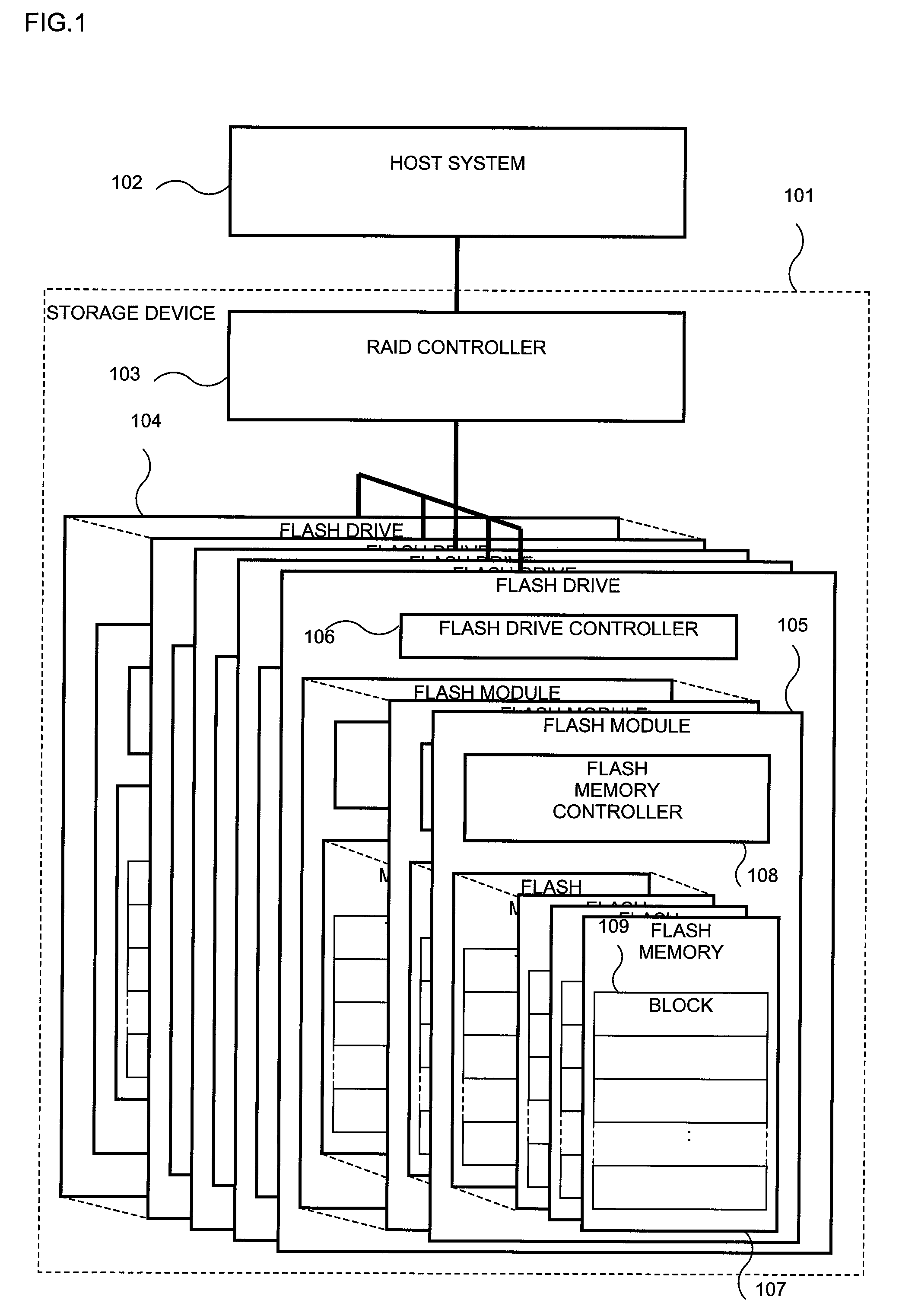
[0038]The first embodiment of the present invention will be described by using FIGS. 1 to 6 and FIGS. 8, 9, and 11. FIG. 1 shows a configuration of a storage device 101 of the embodiment. The storage device 101 includes a plurality of flash drives 104 and a RAID controller 103, which controls the plurality of flash drives 104 in the storage device 101. The storage device 101 is connected to a host system 102 via the RAID controller 103.

[0039]The flash drive 104 includes a plurality of flash modules 105, each of which is a printed board provided with a plurality of flash memory devices 107 and a flash memory controller 108. A flash drive controller 106 interfaces exchanges between the flash module 105 and the RAID controller 104, the superior controlling unit of the flash module 105.

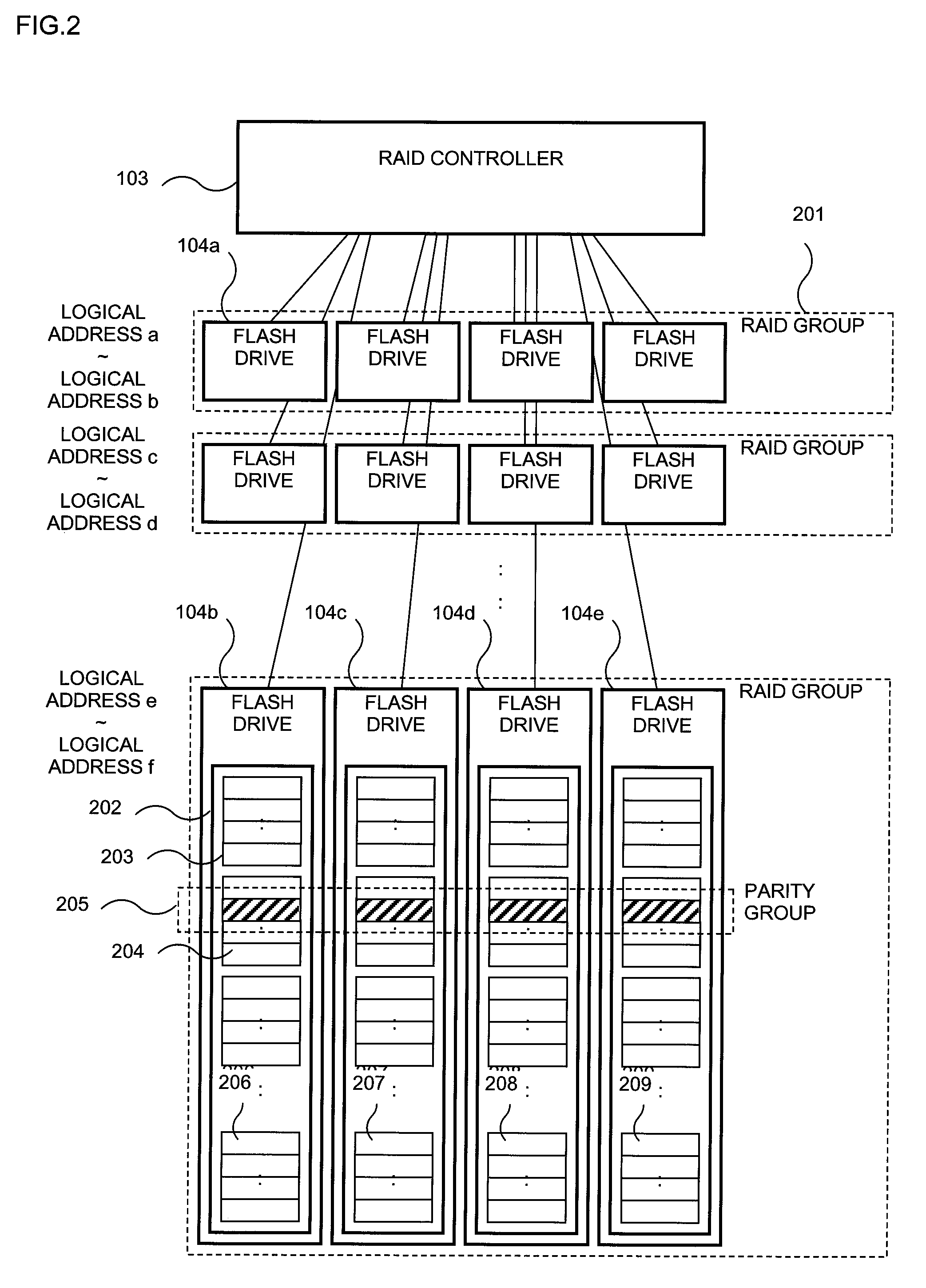
[0040]The storage device 101 that puts much stress on reliability has a plurality of flash drives 104, for example, with four flash drives forming a RAID group 201. The RAID controller 103 allocates a log...

embodiment 2

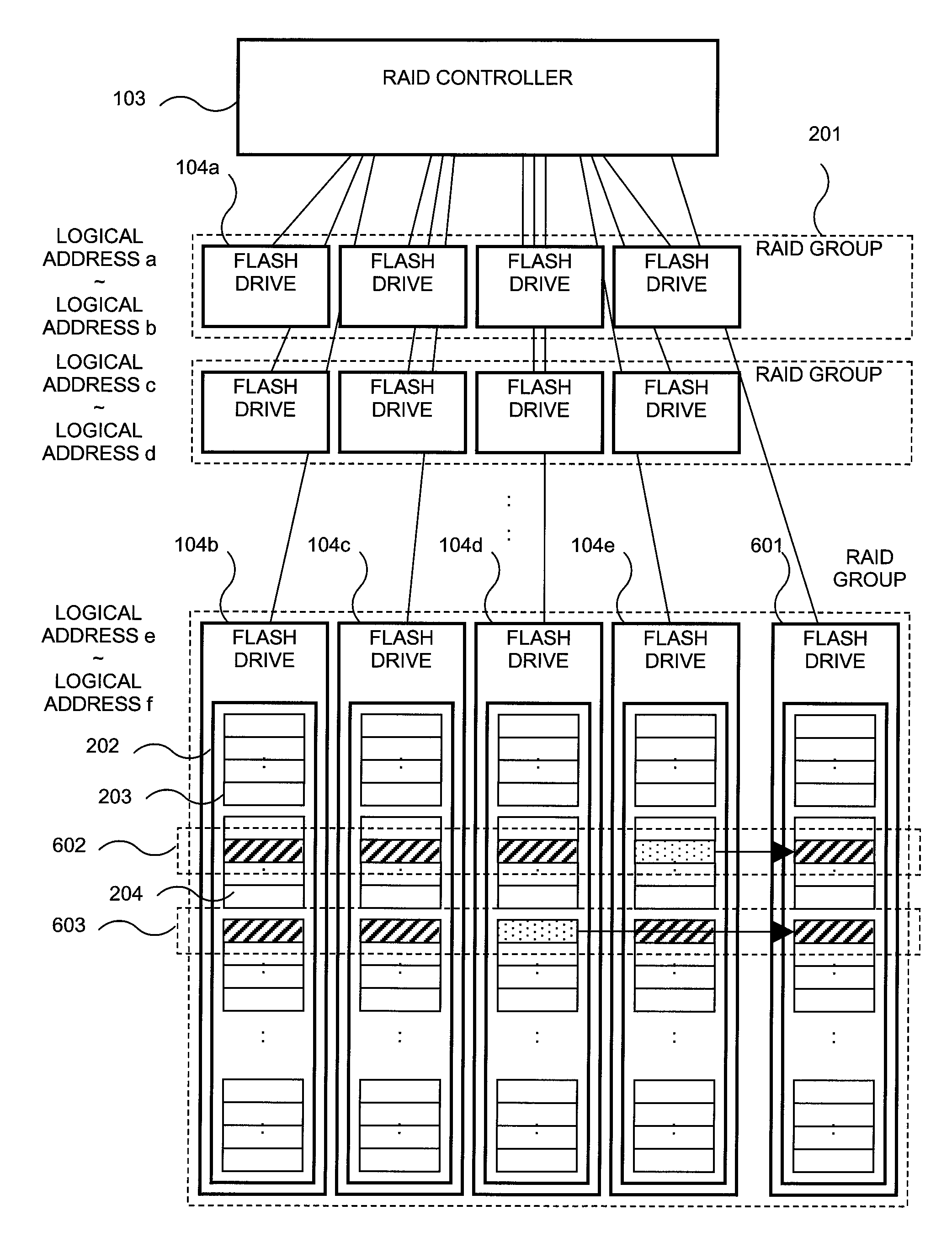
[0075]The same thing can be done also in a flash module in a flash drive. That is to say, before deletion units that cannot to be deleted increase in a flash memory device to make it unable to address writing, a flash module is added and caused to substitute for the flash memory that is unable to address writing.

[0076]The second embodiment of the present invention will be described by using FIGS. 7, 10, and 12. A flash memory is added by the unit of the flash drive in the first embodiment; while a flash memory is added by the unit of a flash module in the flash drive in the second embodiment.

[0077]The flash module has a structure of a printed board provided with a plurality of flash memory devices and a controller for converting a logical address in the flash memory module and a physical address of the flash memory.

[0078]A flash drive controller for controlling a plurality of flash modules is in the flash drive.

[0079]In the first embodiment, the RAID position information is present ...


PUM


Abstract

To enable a capacity of an entire storage device to be kept by adding a flash drive or a flash module in the flash drive for a flash memory that has a failure, even if the storage device using the flash memory has a failure in its part such as a part of flash memory chip has a failure, for example, the flash memory chip has run out of its lifetime. In a storage device 101 equipped with two or more memory device units 105 with a plurality of semiconductor memory devices 107, each of which has a functional capacity unit 109 smaller than a capacity of an entire semiconductor memory device and has a writing lifetime for each functional capacity unit, only a functional capacity unit whose writing lifetime is run out to be determined as unable to be written is substituted by a functional capacity unit in a memory device of the other memory device unit to keep a predetermined capacity of the entire device.

Description

[0001]The present application is based on and claims priority of Japanese patent application No. 2006-286108 filed on Oct. 20, 2006, the entire contents of which are hereby incorporated by reference.BACKGROUND OF THE INVENTION[0002]1. Field of the Invention[0003]The present invention relates to a storage device and a storing method, and more specifically, to a controlling method and an implementing method of a flash memory for enhancing reliability of a storing system using a flash memory.[0004]2. Description of the Related Art[0005]As a non-volatile semiconductor memory, there is a flash memory for which a deletion unit or a writing unit (functional capacity unit) is previously determined. The flash memory has a floating gate structure, which wraps a conductor such as a polysilicon in an oxide insulator such as an oxide silicon for storing information by the presence of the charge, which is in the floating gate. The flash memory may use a structure for reserving a charge in a parti...

Claims


Application Information

Patent Timeline
Patent Type & Authority Patents(United States)
IPC IPC(8): G06F12/06
CPCG11C16/3495G11C29/76G11C29/765G06F3/0688G06F3/0616G06F3/064
Inventor KITAHARA, JUN
Owner HITACHI LTD
Why Eureka
Try Eureka