
Remote inspection device

a remote inspection and optical fiber cable technology, applied in the field of optical devices, can solve the problems of high cost of borescopes and similar optical scopes that use optical fiber cables, and relatively high cos

Active Publication Date: 2010-07-20
INSPECTRON MASSACHUSETTS
View PDF38 Cites 119 Cited by
  • Summary
  • Abstract
  • Description
  • Claims
  • Application Information

AI Technical Summary

Problems solved by technology

This requirement contributes to the high cost of borescopes and similar optical scopes that use optical fiber cables.
When using borescopes and similar optical scopes objects in dark areas illumination is commonly provided by means of a strong and relatively expensive halogen light source projected down the cable from the observation end.

Method used


Image

  • Remote inspection device
  • Remote inspection device
  • Remote inspection device

Examples


Embodiment Construction

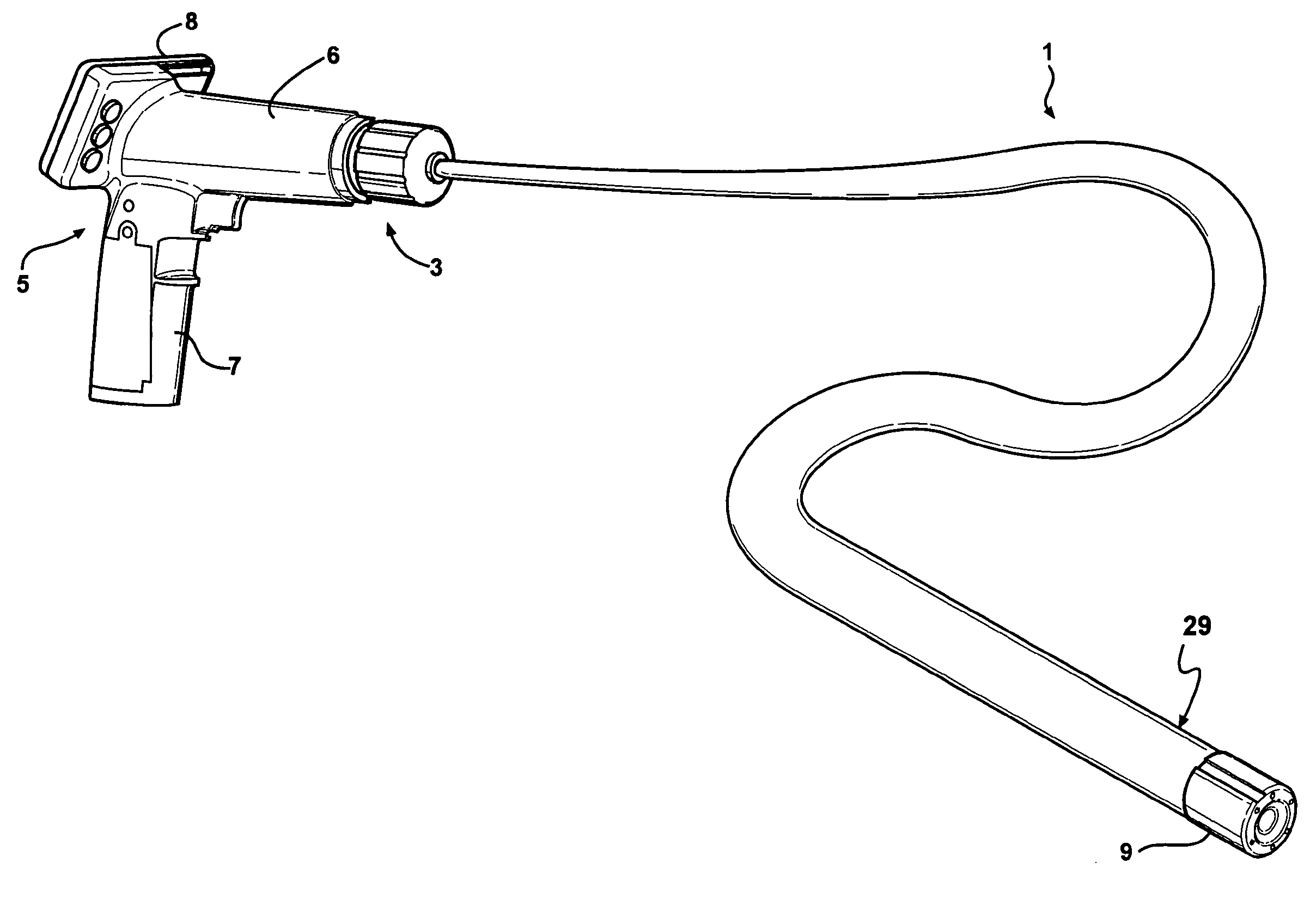
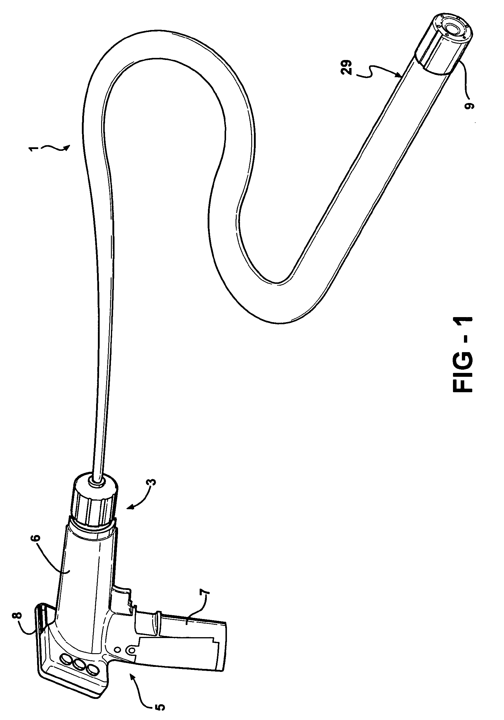
[0035]The present invention is directed to solid state optical snake devices for observing and / or manipulating and / or retrieving objects in remote sites or locations which can be used with a number of attachments that are designed and configured to manipulate and / or retrieve various objects that, due to their presence in remote situs, are otherwise inaccessible.

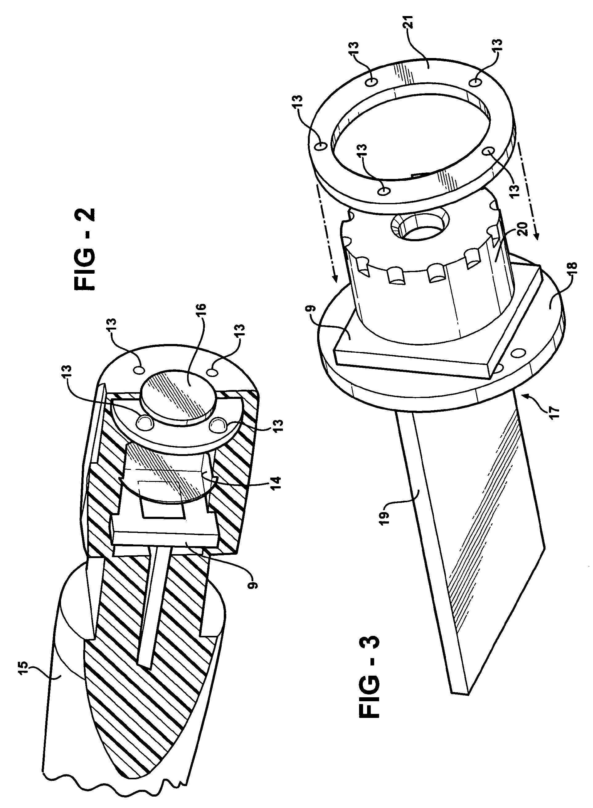
[0036]The reference to “solid state” as used herein is intended to distinguish the present optical devices from known optical devices that include optical fiber bundles as discussed above. Rather than use an optical fiber bundle, the optical devices of the present invention use a flexible cable through which signal transmitting wires extend and which flexible cable provides support for a number of different attachments that can be removably coupled and interchanged on the distal end of the optical devices.

[0037]In addition to being configured to support a number of different attachments, the distal end of the flexible cable i...


PUM


Abstract

An integrated solid state device for viewing and manipulating objects located in remote sites and locations which includes a flexible cable having a camera on one end and a viewer on an opposite end. The camera captures images near the end of the flexible cable and converts the images into a video signal that is transferred through wires that extend through the length of the flexible cable. The video signals are received by the viewer and converted into a displayed image. A variety of removable article manipulators can be attached to the distal end of the flexible cable and used to manipulate, capture and retrieve articles and objects near the distal end of the flexible cable.

Description

RELATED APPLICATIONS[0001]The present invention is a Continuation-In-Part of U.S. patent application Ser. No. 11 / 032,275, filed Jan. 10, 2005 now abandoned of which the entire specification is expressly incorporated herein by reference and to which priority is claimed under 35 U.S.C. §120.TECHNICAL FIELD[0002]The present invention relates to an optical device for observing remote sites and locations that have limited access. More specifically, the present invention is directed to an optical device that can be used for observing, manipulating and retrieving objects in remote sites and locations which optical device can include different attachments and configurations.BACKGROUND ART[0003]When inspecting the interior of engine cylinders at automotive equipping plants, repair shops, etc., a borescope is commonly inserted through a spark plug hole and used to inspect the interior of a cylinder without going through all the trouble of removing the engine's cylinder head(s). Borescopes are...

Claims


Application Information

Patent Timeline
Patent Type & Authority Patents(United States)
IPC IPC(8): A61B1/00A61B1/04
CPCA61B1/00052G02B23/2476G02B23/2484
Inventor PEASE, ALFRED A.BOEHNLEIN, ALNEWMAN, TYEECKHOFF, PAUL J.
Owner INSPECTRON MASSACHUSETTS
Learn More