

Digital video signal inter-block interpolative predictive encoding/decoding apparatus and method providing high efficiency of encoding
a technology of predictive encoding and video signal, applied in the direction of color television with bandwidth reduction, television system, instruments, etc., can solve the problems of low rate of occurrence of code errors, difficult method for such a method, and large adverse effect of displaying video images
- Summary
- Abstract
- Description
- Claims
- Application Information
AI Technical Summary
Benefits of technology
Problems solved by technology
Method used
Image

Examples
first embodiment
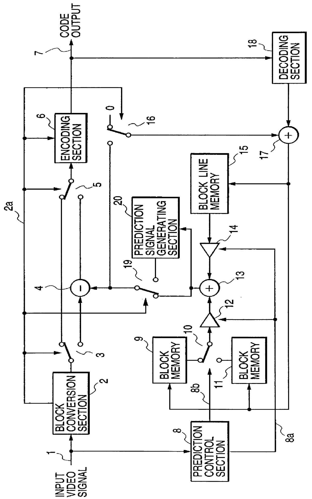
an inter-block interpolative prediction encoding apparatus according to the present invention will be described referring to the general system block diagram of FIG. 1. In FIG. 1, a usual type of raster-scan digital video signal is supplied to an input terminal 1, and resultant code is supplied to an output terminal 7. A subtractor 4 and prediction adder 17 perform basically the same functions as the correspondingly designated components in the prior art example of FIG. 16 described above. In addition, this embodiment includes a block conversion section 2, switches 3, 5, 10 and 16, and encoding section 6, block memories 9, 11 and a block line memory 15, multipliers 12 and 14 and adder 13, a prediction signal generating section 20, and prediction control section 8 and an decoding section 18. The operation of each of the block conversion section 2, the encoding section 6, the prediction control section 8 and the decoding section 18 differs substantially from that of the block conversi...
second embodiment
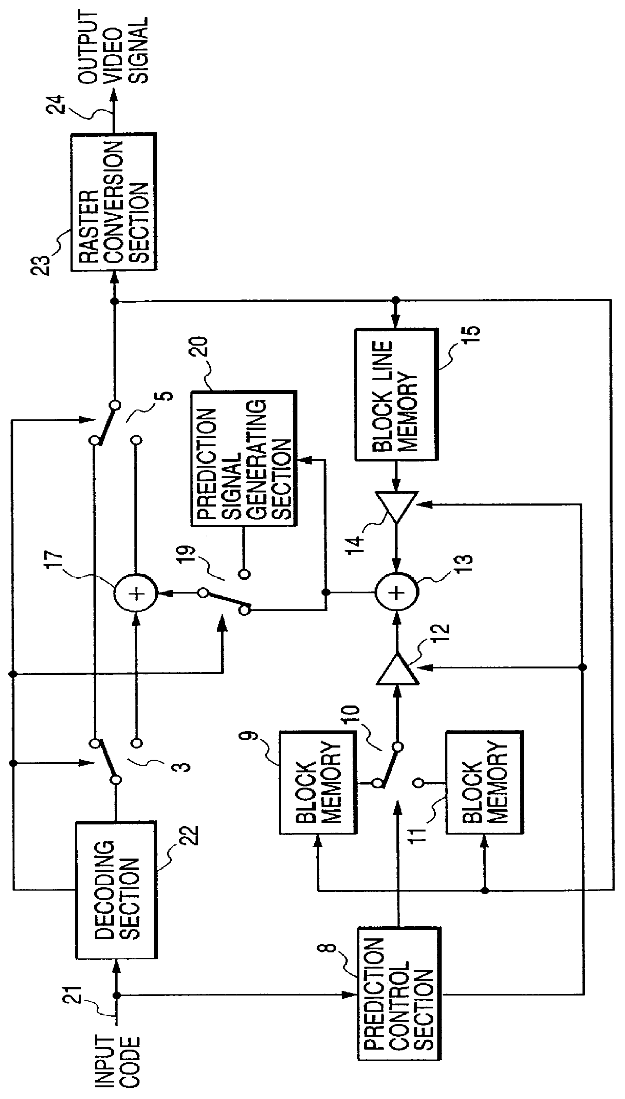
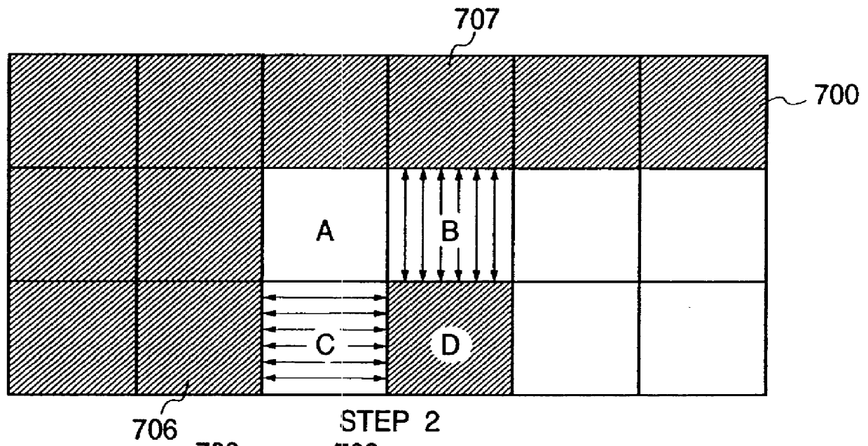
an inter-block interpolative prediction encoding apparatus according to the present invention will be described, referring to the general system block diagram of FIG. 9. In FIG. 9, components having identical functions to components of the embodiment of FIG. 1 are designated by identical reference numerals to those of FIG. 1, and detailed description of these will be omitted. The overall operation of this embodiment is substantially identical to that of the embodiment of FIG. 1, differing only with respect to the encoding of each A-block, of each of the sets of four A, B, C and D-blocks which are sequentially processed as described above referring to FIG. 3. Essentially, this embodiment differs from that of FIG. 1 by implementing adaptive prediction. To achieve this, the embodiment includes an encoding efficiency judgement section 33, which is utilized to determine whether the interpolated pixel values for an A-block are to be derived by interpolation along the horizontal or the ver...
PUM
 Abstract
Description
Claims
Application Information