Eureka AIR delivers breakthrough ideas for toughest innovation challenges, trusted by R&D personnel around the world.

Camera system having converting means, recording means, reproduction means, plate-shaped display and protection means

a technology of converting means and recording means, applied in the field of image recording systems, can solve the problems of high temperature, inability to obtain the reproduction image and limit the discussion of their features, and achieve the effect of optimum tone-reproduction quality

Inactive Publication Date: 2006-04-18
CANON KK
View PDF7 Cites 115 Cited by
  • Summary
  • Abstract
  • Description
  • Claims
  • Application Information

AI Technical Summary

Benefits of technology

[0013]A further object of the present invention is to provide a playback device which enables the operator to monitor the image during the recording operation, or to reproduce the once recorded image.

Problems solved by technology

These prior art systems, however, places a limit of the discussion for their features on the mere function of recording the image signals on the magnetic recording medium, and disclose nothing about the exposure level control in producing the image signals.
For this reason, the prior art system tends to record some of the image signals in an over-exposed state, and some in an under-exposed state, so that the reproduced image of optimum tone-reproduction quality cannot be obtained.
But, because these devices are fabricated in the form of integrated circuits on a silicon semi-conductor substrate of thin thickness, when the image-receiving surface of the solid state device is accidentally exposed to a very intense radiant energy particularly from the sun through the image forming optical system, there is a high possibility of occurrence of suddenly heating the exposed surface of the device in a portion thereof to so high a temperature that the solid state device is burned to damage.
Another disadvantage of the prior art system is that the recorded image is monitored by making use of an optical finder similar to that in the conventional photographic camera.

Method used


Image

  • Camera system having converting means, recording means, reproduction means, plate-shaped display and protection means
  • Camera system having converting means, recording means, reproduction means, plate-shaped display and protection means
  • Camera system having converting means, recording means, reproduction means, plate-shaped display and protection means

Examples


Embodiment Construction

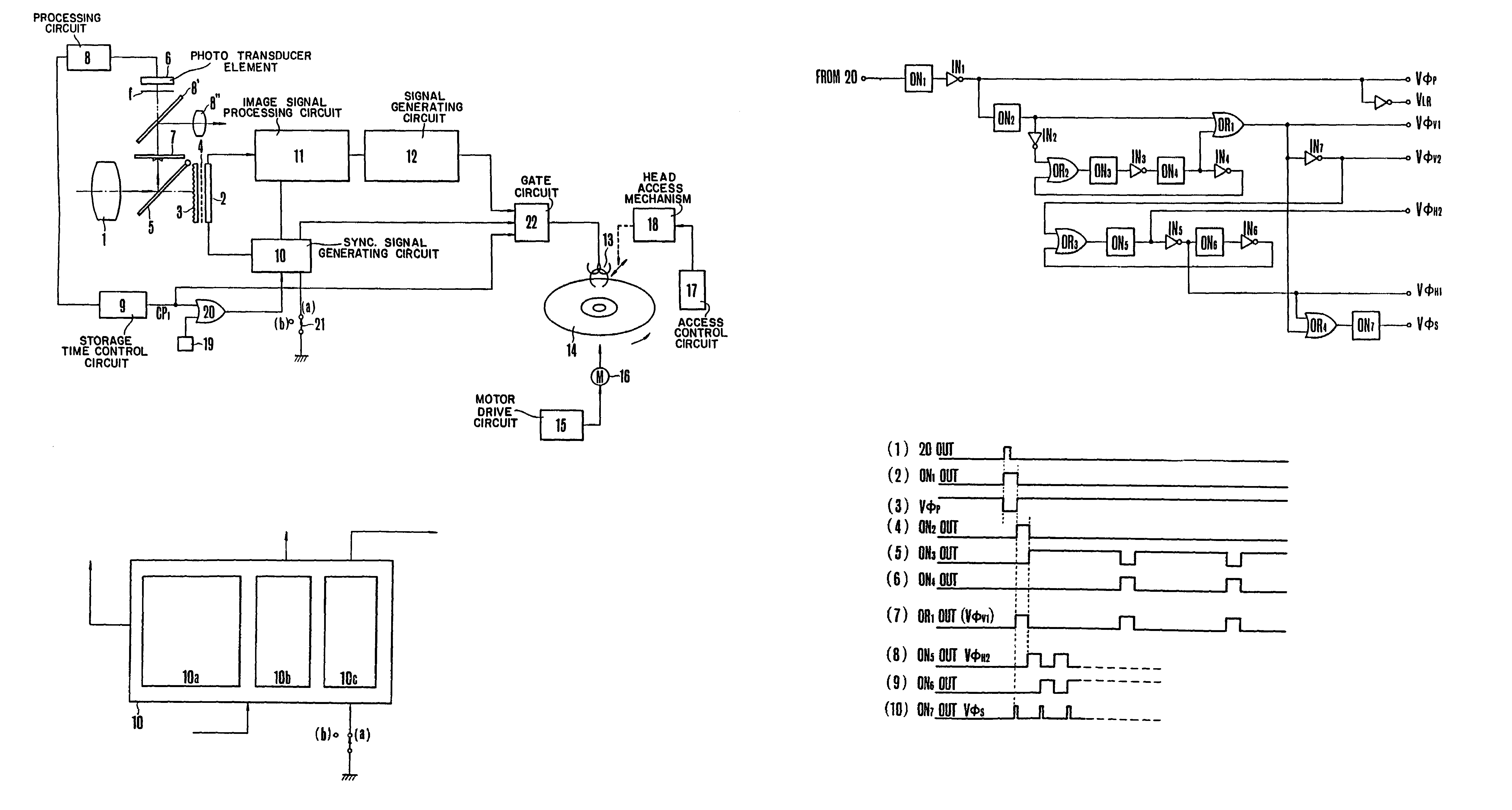
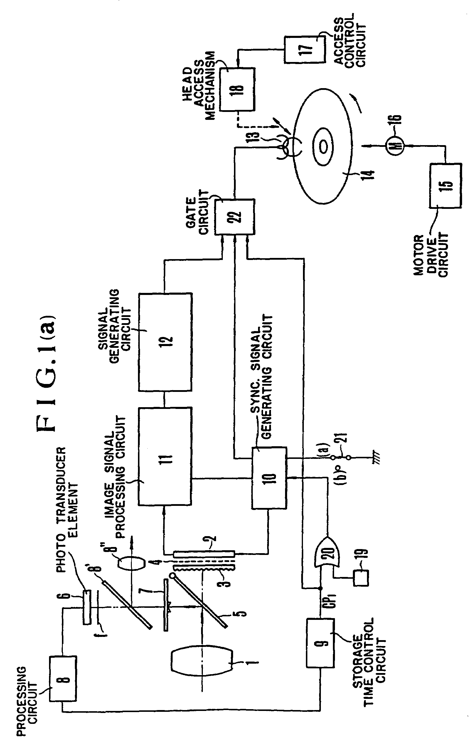
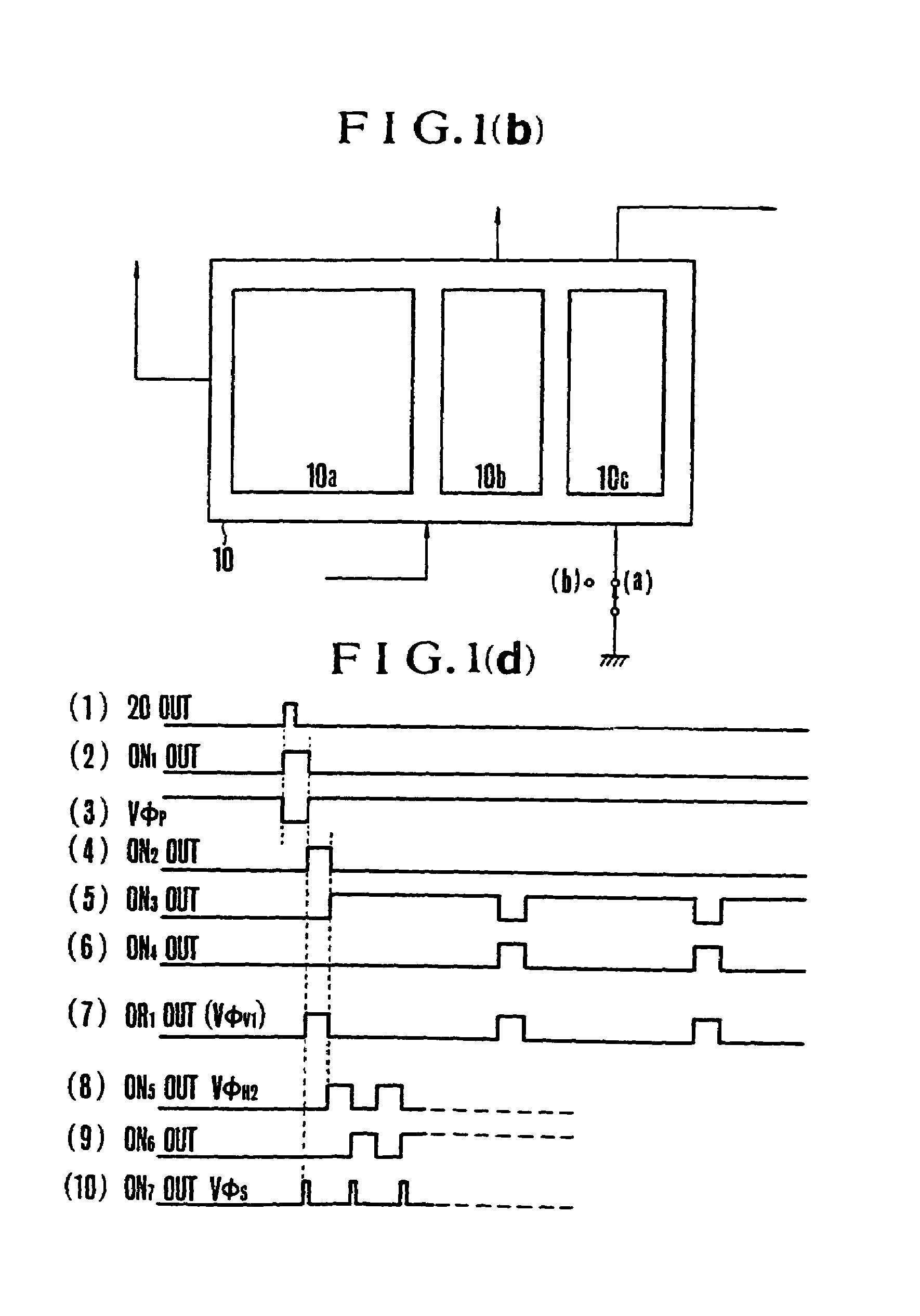
[0053]Referring to FIGS. 1 to 6, there is shown an embodiment of an image recording system according to the present invention. In FIG. 1(a), 1 is an optics for forming an image of an object (not shown) on a focal plane near an image-receiving surface of a solid state image transducer 2 such as CCD available, for example, from Fairchild Camera & Inst. under the tradename of CCD202. Positioned on the device 2 are a lenticular screen 3 and a color filter 4 arranged in this order from the front to detect color information of the object. A portion of the light emerging from the optics 1 is reflected by a half-mirror 5 to a focusing screen where an image of the object is formed. Light from the image on the screen 7 is radiated upward to a light measuring or photoelectric element 6 such as silicon photo-cell through a beam splitter 8′ and a luminosity factor correction filter, f, the one of the light from the image which is splitted entering an eye-piece 8″.

[0054]As shown in FIGS. 2(a) and...


PUM


Abstract

A camera system comprising means for converting an object image into an image signal, recording means for recording the image signal on a recording medium, reproduction means for reproducing the image signal recorded on the recording medium, finder means for displaying the object image and display means for selectively displaying an image corresponding to the image signal to be recorded or an image corresponding to the reproduced image signal. A display portion of the finder means is smaller than that of the display means and the display portion of the display means has a flat plate which can be exposed to an outside of the camera system.

Description

[0001]This is a divisional application of Ser. No. 08 / 265,706, filed Jun. 24, 1994, now U.S. Pat. No. 5,923,367 which in turn is a continuation application of application Ser. No. 08 / 156,523, filed Nov. 19, 1993, now abandoned which in turn is a continuation application of application Ser. No. 07 / 918,329, filed Jul. 22, 1992, now abandoned which in turn is a divisional application of application Ser. No. 07 / 740,865, filed Jul. 31, 1991, now U.S. Pat. No. 5,191,435 which in turn is a continuation application of application Ser. No. 07 / 503,145, filed Mar. 30, 1990, now abandoned which in turn is a divisional application of application Ser. No. 07 / 309,349, filed Feb. 10, 1989, which issued as U.S. Pat. No. 4,928,184 on May 22, 1990, which in turn is a continuation application of application Ser. No. 07 / 004,148, filed Jan. 16, 1987, which issued as U.S. Pat. No. 4,823,200 on Apr. 18, 1989, which in turn is a divisional application of application Ser. No. 06 / 347,966, filed Feb. 11, 1982,...

Claims


Application Information

Patent Timeline
IPC IPC(8): H04N5/222H04N5/76
CPCH04N5/23293H04N5/772H04N9/83H04N5/781H04N23/53H04N23/55H04N23/63
Inventor TSUNEKAWA, TOKUICHIDATE, NOBUAKIAIZAWA, HIROSHIHOSOE, KAZUYAURUSHIBARA, KAZUNORI
Owner CANON KK
Why Eureka
Eureka Blog
Learn More