Reflecting optical element with eccentric optical passageway
What is Al technical title?
Al technical title is built by PatSnap Al team. It summarizes the technical point description of the patent document.
a technology of optical passageway and optical element, applied in the field of optical element and optical element unit, can solve the problems of deteriorating imaging accuracy and less compact design, and achieve good and long-term reliable imaging properties
Active Publication Date: 2010-07-20
CARL ZEISS SMT GMBH
View PDF15 Cites 12 Cited by
Summary
Abstract
Description
Claims
Application Information
AI Technical Summary
This helps you quickly interpret patents by identifying the three key elements:
Problems solved by technology
Method used
Benefits of technology
[0011]It is thus an object of the invention to, at least to some extent, overcome the above disadvantages and to provide good and long term reliable imaging properties of a compact optical system used in an exposure process.
[0012]It is a further object of the invention to reduce the effort necessary for an optical system used in an exposure process while at least maintaining the imaging accuracy of the optical system used in an exposure process.
[0013]It is a further object of the invention to reduce the effort necessary for supporting an optical element having a reflective area used in an exposure process and deviating from rotational symmetry.
[0014]These objects are achieved according to the invention which is based on the teaching that a reduction of the effort necessary for a support avoiding introduction of excessive stresses and, thus, deformations into an optical element having a reflective area used in an exposure process is possible by providing an optical element with an optical element body that is, in itself, rotationally symmetric with respect to an axis of rotational symmetry and to provide this optical element body with an optical passageway that allows light to pass the optical element body and is arranged eccentrically with respect to the axis of rotational symmetry of the optical element body.
[0015]Thus, a very compact arrangement with an optical element may be achieved that allows passage of the exposure light via the optical passageway but—eventually apart from the optical passageway—still has a substantially rotationally symmetric optical element body that allows simple stress and deformation minimized support.
Problems solved by technology
A problem that arises especially with the above optical elements having reflective areas or reflective surfaces deviating from rotational symmetry is to provide support to the optical element without introducing excessive stresses and, thus, deformations into the optical element which otherwise would deteriorate the imaging accuracy.
However, this rotationally symmetric design of the mirrors has the disadvantage that they require more space, not only for the respective mirror itself but also for the light that has to pass the respective mirror on its outside, leading to a less compact design.
Method used
Image
Click on the blue label to locate the original text in one second.
Reading with bidirectional positioning of images and text.
Examples
Embodiment Construction
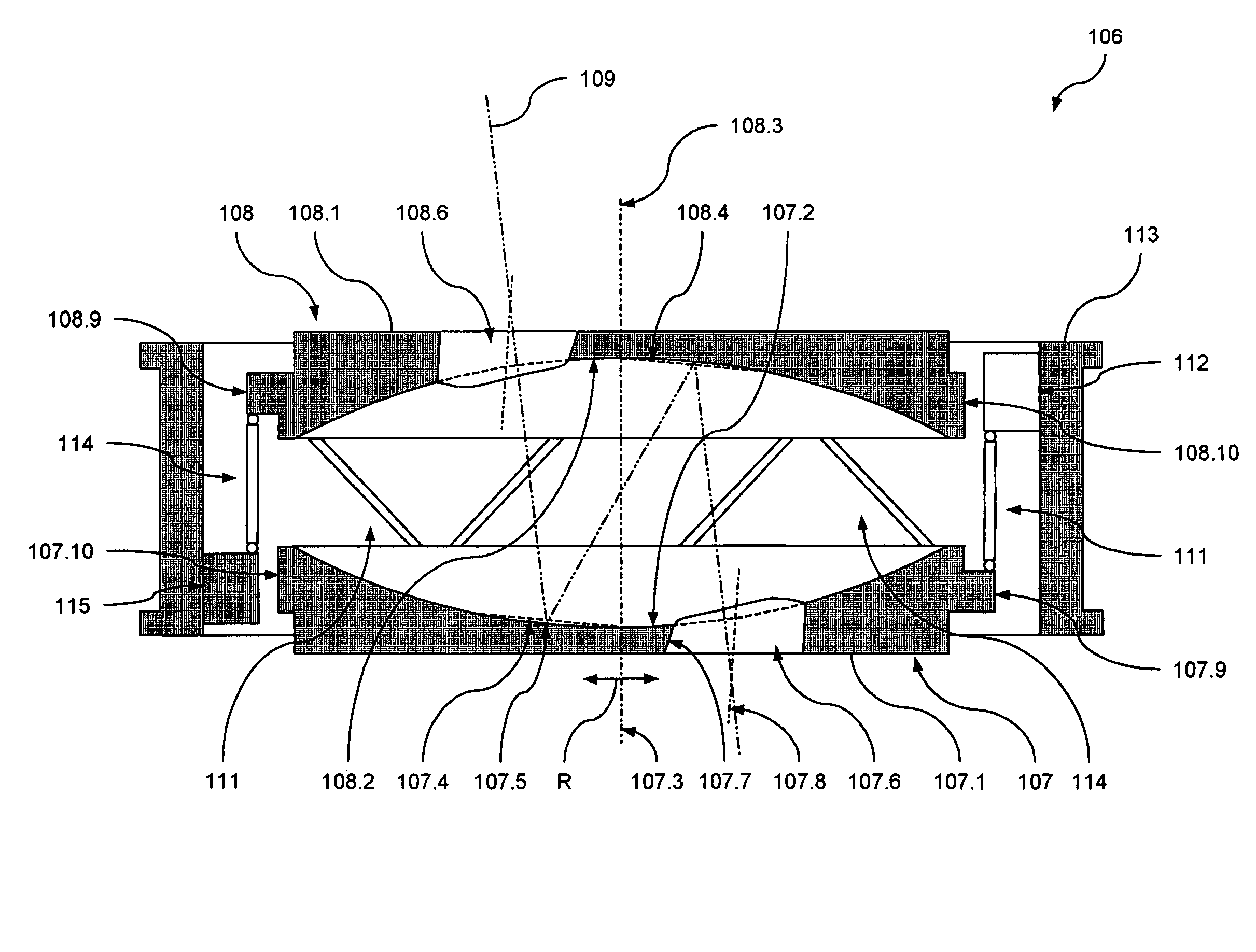
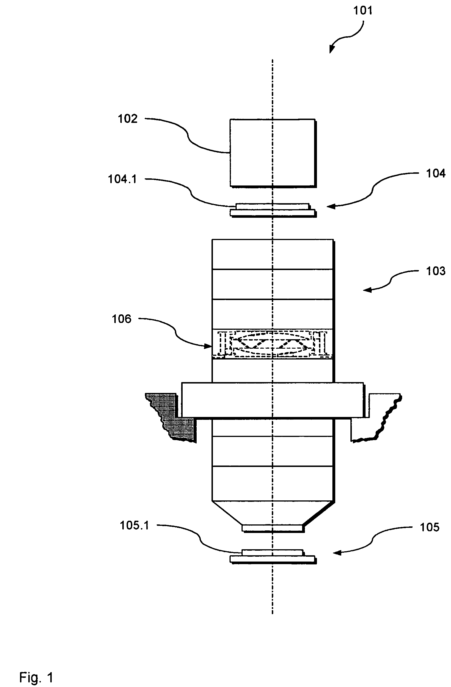
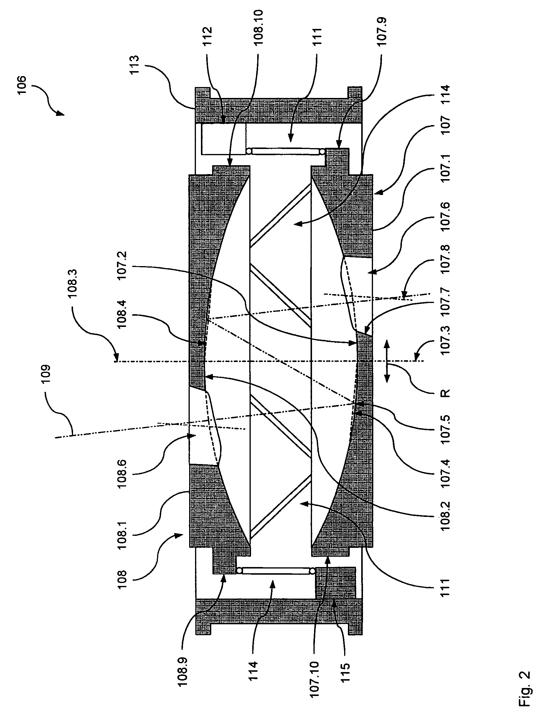
[0033]In the following, a preferred embodiment of an optical imaging arrangement 101 according to the invention will be described with reference to FIGS. 1 to 3.
[0034]FIG. 1 is a schematic and not-to-scale representation of the optical imaging arrangement in the form of an optical exposure apparatus 101. The optical exposure apparatus 101 comprises an illumination unit 102 and an optical projection unit 103 adapted to transfer, in an exposure process, an image of a pattern formed on a mask 104.1 of a mask unit 104 onto a substrate 105.1 of a substrate unit 105. To this end, the illumination unit 102 illuminates the mask 104.1. The optical projection unit 103 receives the light coming from the mask 104.1 and projects the image of the pattern formed on the mask 104.1 onto the substrate 105.1, e.g. a wafer or the like.
[0035]The optical projection unit 103 comprises a catadioptric optical element system including a plurality of refractive elements, such as lenses or the like, and a plur...
PUM
Abstract
There is provided an optical element comprising an optical element body, a reflecting area and an optical passageway. The optical element body defines an axis of rotational symmetry. The reflecting area is disposed on the optical element body and adapted to be optically used in an exposure process. The optical passageway is arranged within the optical element body and allows light to pass the optical element body, the optical passageway being arranged eccentrically with respect to the axis of rotational symmetry.
Description
CROSS-REFERENCE TO RELATED APPLICATIONS[0001]The present application is (a) a continuation-in part of International Patent Application Serial No. PCT / EP2003 / 013606, filed Dec. 3, 2003, and (b) a continuation-in-part of International Patent Application Serial No. PCT / EP2005 / 005600, filed May 24, 2005.[0002]The present application is also claiming priority of German Patent Application No. 103 46 046, filed Oct. 2, 2003, and German Patent Application No. 10 2004 025 832, filed May 24, 2004.[0003]The entire content of the four aforementioned applications is herein incorporated by reference.BACKGROUND OF THE INVENTION[0004]The invention relates to optical elements and optical element units used in exposure processes, in particular to optical elements and optical element units used in microlithography systems. It further relates to methods of manufacturing and of supporting an optical element of such an optical element arrangement. It also relates to optical imaging methods for transferri...
Claims
Application Information
Patent Timeline
Application Date:The date an application was filed.
Publication Date:The date a patent or application was officially published.
First Publication Date:The earliest publication date of a patent with the same application number.
Issue Date:Publication date of the patent grant document.
PCT Entry Date:The Entry date of PCT National Phase.
Estimated Expiry Date:The statutory expiry date of a patent right according to the Patent Law, and it is the longest term of protection that the patent right can achieve without the termination of the patent right due to other reasons(Term extension factor has been taken into account ).
Invalid Date:Actual expiry date is based on effective date or publication date of legal transaction data of invalid patent.