
Interface switch for use with fibre channel fabrics in storage area networks

a technology of interface switches and fibre channel fabrics, applied in data switching networks, multiplex communication, digital transmission, etc., can solve problems such as performance issues or even fabric segmentation, and achieve the effect of promoting scalability within each enterprise fabri

Inactive Publication Date: 2010-07-20
AVAGO TECH INT SALES PTE LTD
View PDF31 Cites 17 Cited by
  • Summary
  • Abstract
  • Description
  • Claims
  • Application Information

AI Technical Summary

Benefits of technology

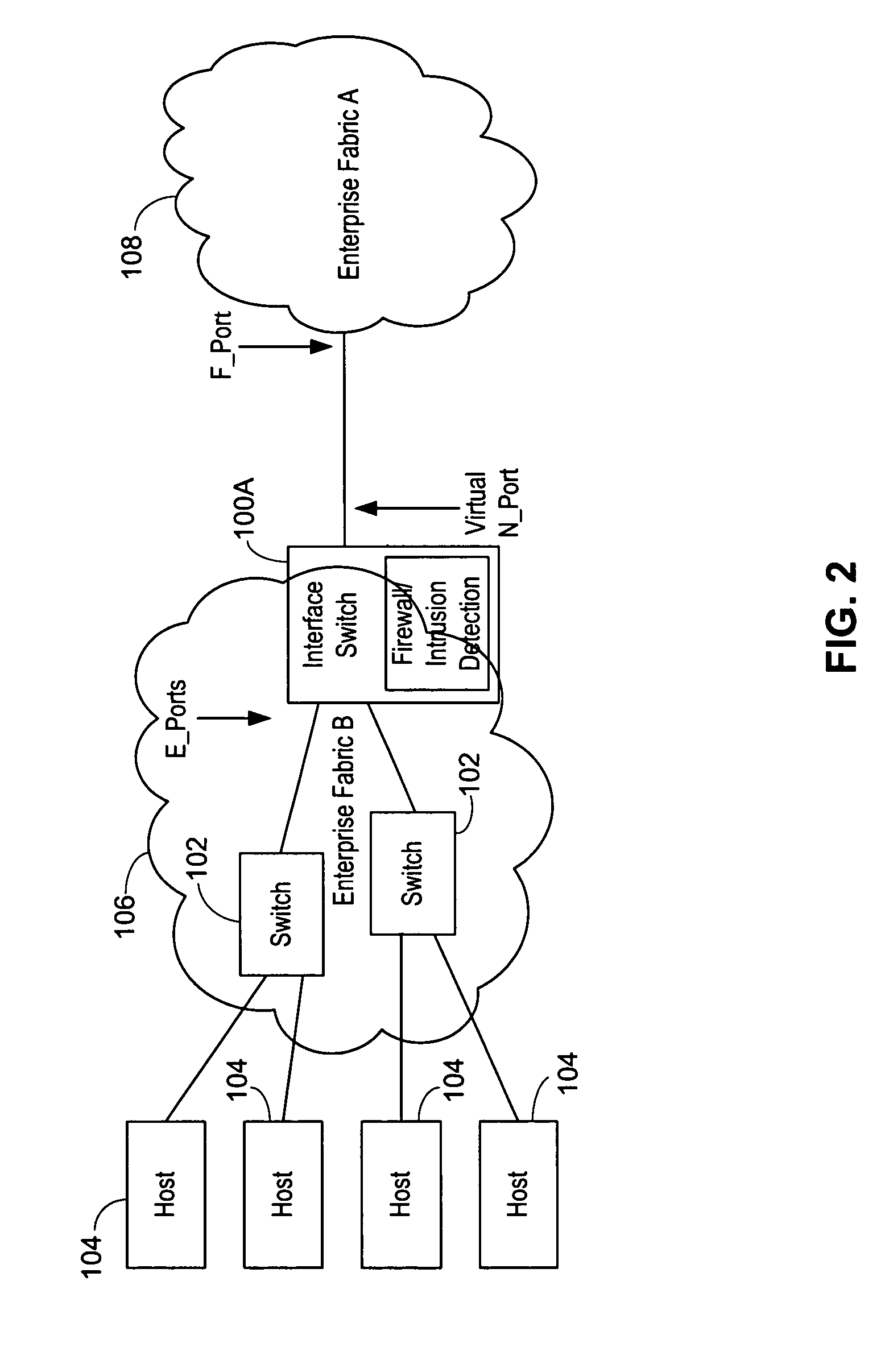
[0008]The use of N_port virtualization also enables the interface switch to act as an initiator, which is advantageous as this allows partitioning of fabrics and isolation between the two enterprise fabrics for exchanges originating on one of the enterprise fabrics. Since the enterprise fabrics are not directly connected, the two enterprise fabrics are isolated from large amounts of fabric activity coming from other enterprise fabrics. This isolation promotes scalability within each enterprise fabric. Additionally, this isolation avoids merging the two enterprise fabrics, which could result in performance issues or even fabric segmentation. Since the interface switch may preferably be a single conduit between the enterprise fabrics, it is also a good point to enforce perimeter defenses (similar to a firewall) against attacks, either intentional or resulting from misbehaviors. The interface switch may also act as a throttle by controlling the accesses between the enterprise fabrics. Further, the interface switch may act as a protocol gateway.

Problems solved by technology

Additionally, this isolation avoids merging the two enterprise fabrics, which could result in performance issues or even fabric segmentation.

Method used


Image

  • Interface switch for use with fibre channel fabrics in storage area networks
  • Interface switch for use with fibre channel fabrics in storage area networks
  • Interface switch for use with fibre channel fabrics in storage area networks

Examples


Embodiment Construction

[0024]This disclosure describes the architecture of an interface switch according to the present invention. The role of an interface switch is to allow connection of fabrics formed by switches of different manufacturers without requiring the use of interoperability mode.

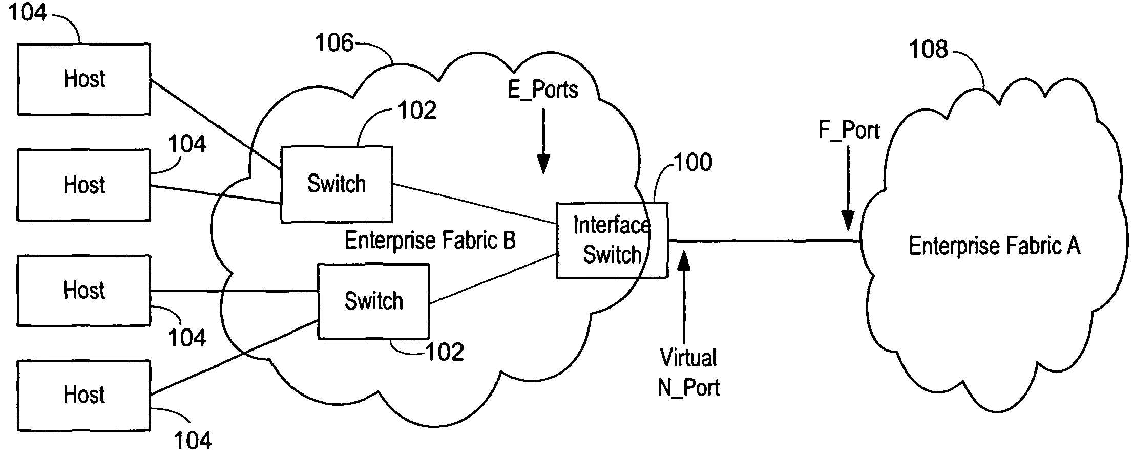
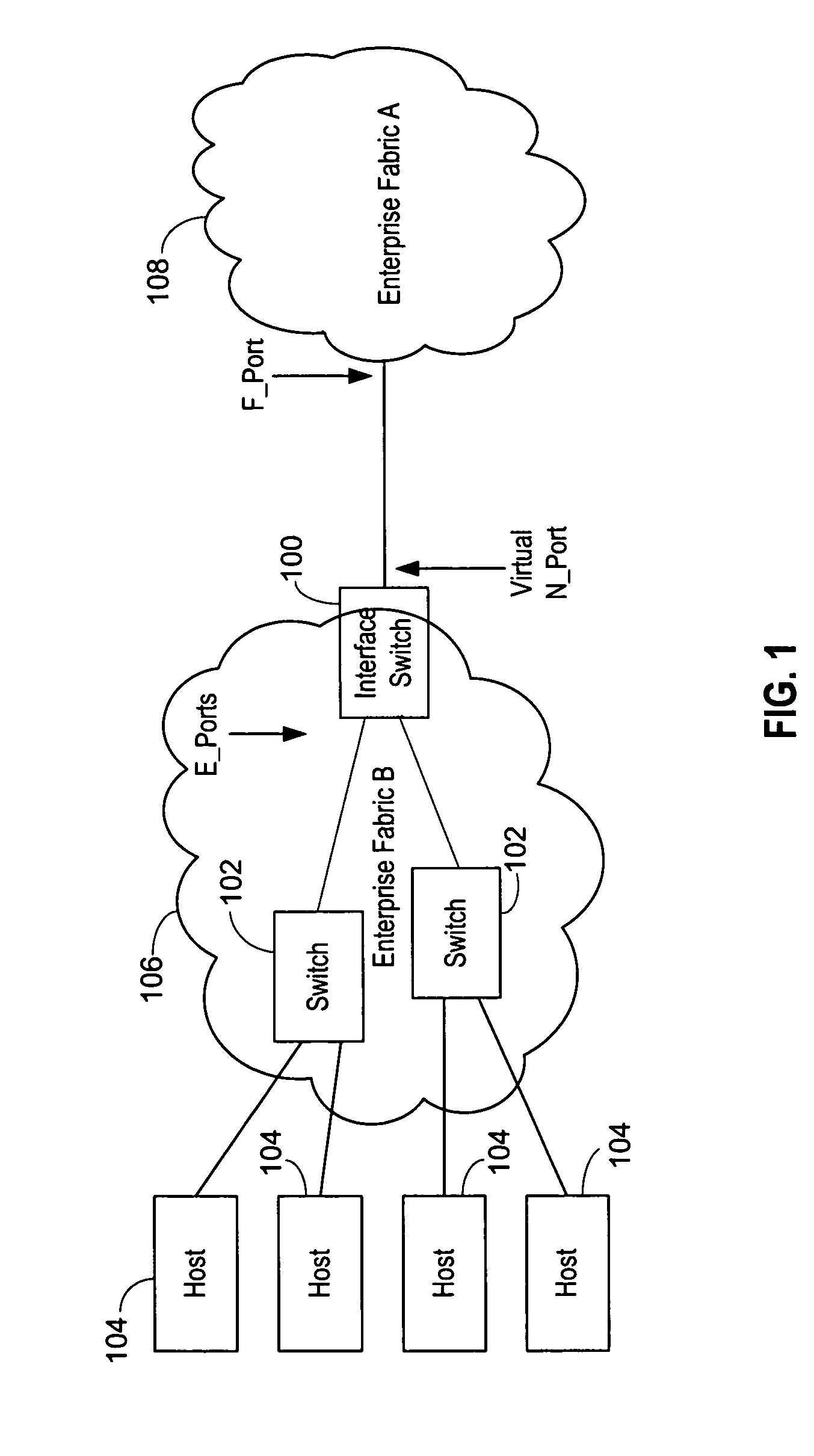
[0025]An interface switch is similar to a conventional switch in that it presents standard inter-switch or E_ports (fabric ports to which other E_ports attach) to the other switches in one enterprise fabric, but different in that it connects to the other enterprise fabric as N_ports (rather than as E_ports) in the preferred embodiment. The interface switch partitions the enterprise storage area network (SAN) into two separate fabrics. FIG. 1 shows a possible deployment of the interface switch 100 connected to switch 102 with a series of hosts 104 which illustrates how two distinct logical fabrics, the enterprise fabric B 106 and the enterprise fabric A 108, are being constructed.

[0026]The interface switch 100 replica...


PUM


Abstract

An interface switch which presents itself as switch to an enterprise fabric formed of the devices from the same manufacturer as the interface switch and that of a host or node to an enterprise fabric from a different manufacturer. This allows each enterprise fabric to remain in a higher performance operating mode. The multiplexing of multiple streams of traffic between the N_ports on the first enterprise fabric and the second enterprise fabric is accomplished by N_port Virtualization. The interface switch can be connected to multiple enterprise fabrics. All control traffic address mappings between virtual and physical addresses may be mediated and translated by the CPU of the interface switch and address mappings for data traffic performed at wire speed. Since the interface switch may preferably be a single conduit between the enterprise fabrics, it is also a good point to enforce perimeter defenses against attacks.

Description

RELATED CASES[0001]This case is related to U.S. patent applications Ser. Nos. 10 / 356,392, entitled “Method and Apparatus for Routing between Fibre Channel Fabrics,” filed Jan. 31, 2003; 10 / 767,405, entitled “Isolation Switch for Fibre Channel Fabrics in Storage Area Networks,” filed Jan. 29, 2004; and 11 / 208,412, entitled “Port Expander for Fibre Channel Fabrics in Storage Area Networks,” filed Aug. 19, 2005, all of which are hereby incorporated by reference.BACKGROUND OF THE INVENTION[0002]1. Field of the Invention[0003]This invention relates to storage area networking using the Fibre Channel protocol. More particularly, it relates to connection of fabrics in storage area networks.[0004]2. Description of the Related Art[0005]The scaling of dynamic Fibre Channel fabrics is a challenging problem. Currently there are compatibility concerns when switches from different manufacturers are used. A defined interoperability mode can be used, but this results in a loss of many of the perform...

Claims


Application Information

Patent Timeline
Patent Type & Authority Patents(United States)
IPC IPC(8): H04L12/50H04J3/16H04L12/28H04L49/111
CPCH04L29/12367H04L29/12377H04L29/12424H04L49/15H04L61/2535H04L49/602H04L61/2514H04L61/2517H04L49/357H04L49/3009
Inventor ATKINSON, MICHAEL W.
Owner AVAGO TECH INT SALES PTE LTD
Learn More