Surface light source device and display device using the same

a technology of surface light source and display device, which is applied in the field of light source, can solve the problems of insufficient display quality, uneven light production, and insufficient light diffusion, and achieve the effects of high light efficiency, sufficient display quality, and high evenness of in-plane luminan

Active Publication Date: 2010-07-27
TRIVALE TECH LLC
View PDF16 Cites 43 Cited by
  • Summary
  • Abstract
  • Description
  • Claims
  • Application Information

AI Technical Summary

Benefits of technology

[0010]The present invention aims to provide a surface light source device having high efficiency of use of light, high evenness of in-plane luminance, and sufficient display quality, and a display device using the same.
[0012]Since, in the surface light source device, the light quantity adjusting means, provided at the bottom part of the recess for adjusting the light from the light source, includes the reflection sheet having a reflection function for reflecting the light from the light source and a transmission function in which the total light transmittance t satisfies t≧πr2 cos θ / {(1−cos θ)(S−πr2)}, the surface light source device according to the present invention provides effects of enhancing efficiency of use of light, enhancing evenness of in-plane luminance, and providing sufficient display quality.
[0014]The display device according to the present invention provides effects of enhancing efficiency of use of light, enhancing evenness of in-plane surface luminance, and providing sufficient display quality.

Problems solved by technology

Therefore, the conventional surface light source device can reduce quantity of light directly emitted from the light source and produce luminous unevenness.
Therefore, when uniform in-plane luminance is further demanded, sufficient display quality cannot be obtained from the conventional surface light source device.
Therefore, the light is not fully diffused, thereby entailing a problem that luminous unevenness is generated ahead of the light source.

Method used


Image

  • Surface light source device and display device using the same
  • Surface light source device and display device using the same
  • Surface light source device and display device using the same

Examples


embodiment 1

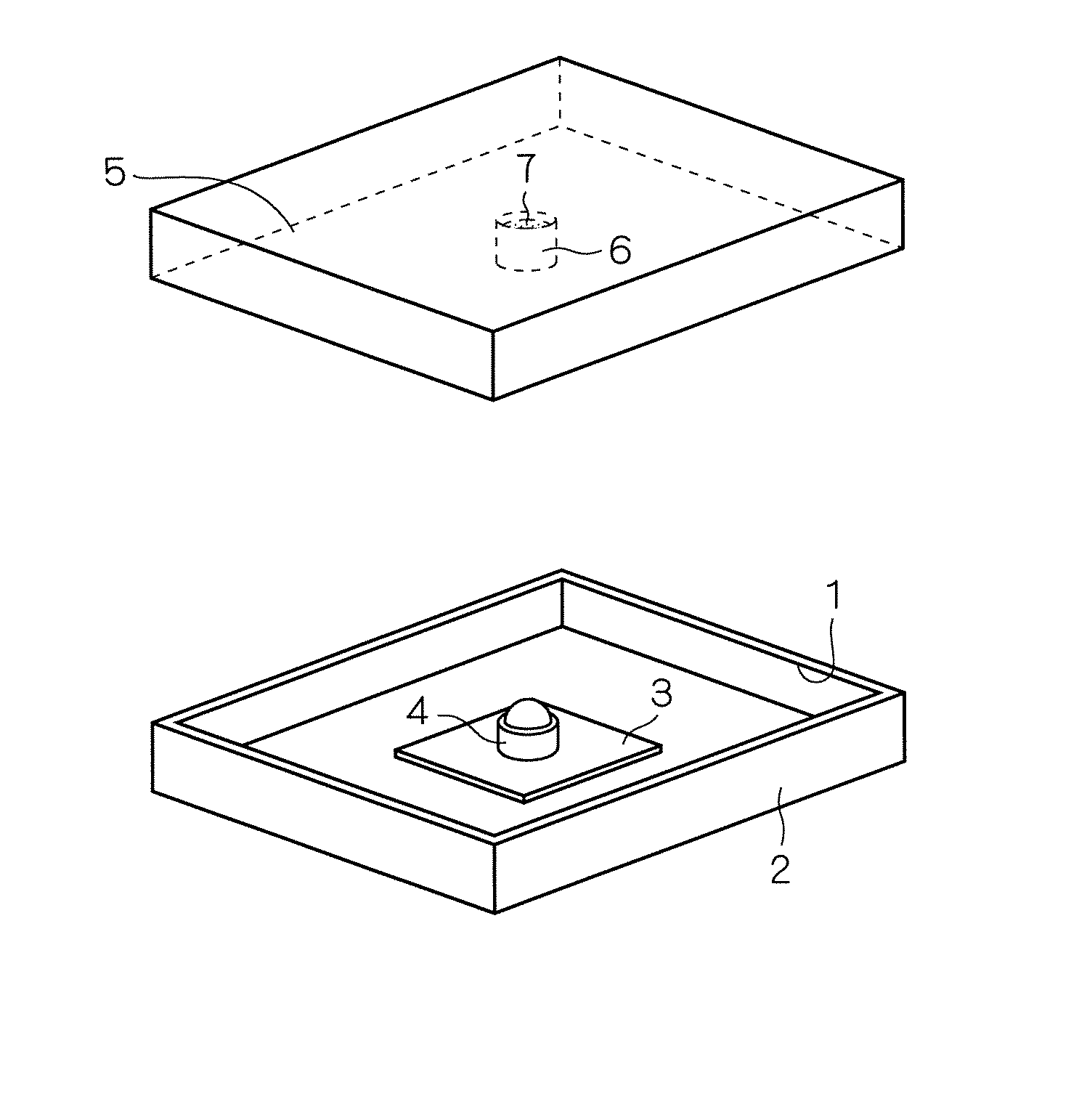
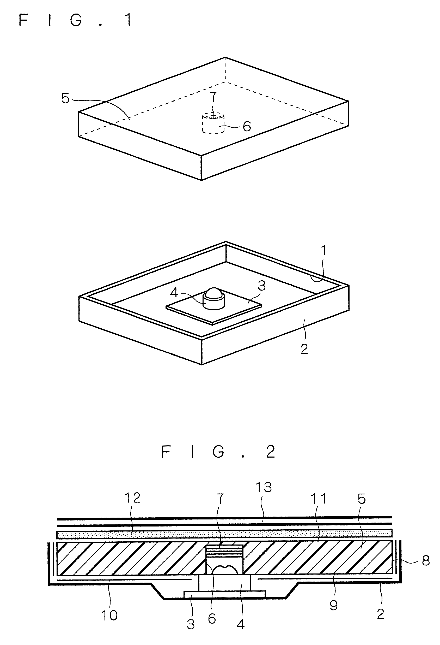
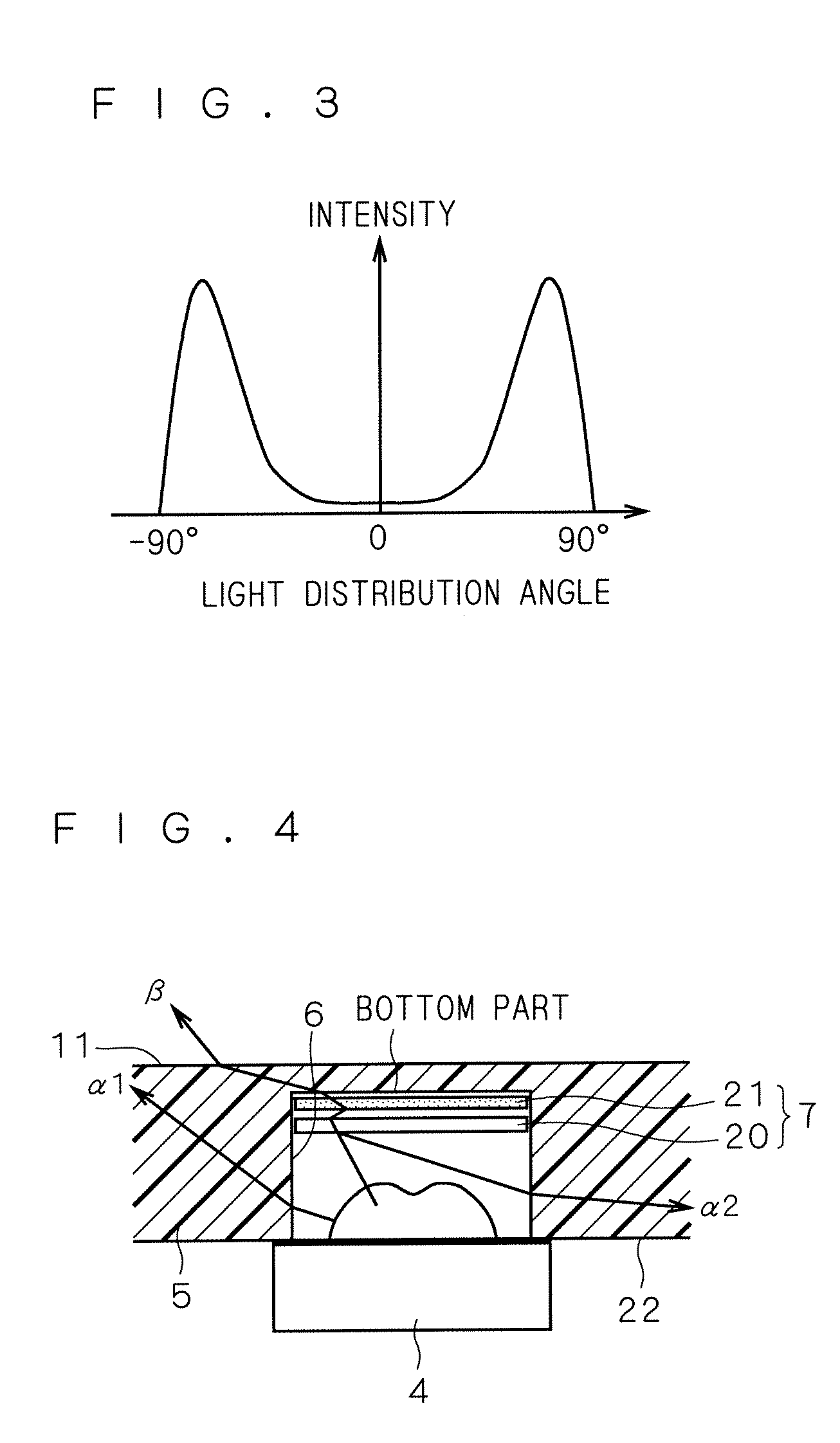
[0026]FIG. 1 is an exploded perspective view of a first embodiment of a surface light source device according to the present invention. FIG. 2 is a sectional view of the first embodiment of the surface light source device according to the present invention. The surface light source device shown in FIG. 1 has a housing 2 having an opening 1 formed at its one face, an LED (Light Emitting Diode) light source 4 held at the face opposite to the opening 1 through an LED substrate 3, a light guiding plate 5 disposed at the position for covering the opening 1 and the LED light source 4, a cylindrical recess 6 formed at the position of the light guiding plate 5 corresponding to the LED light source 4, and light quantity adjusting means 7 provided at the bottom part of the recess 6. As apparent from FIG. 2, a part of the LED light source 4 is housed in the recess 6.

[0027]A reflection sheet 10 is provided between the light guiding plate 5 and the housing 2 (at the side face 8 and the reflectio...

embodiment 2

[0067]FIG. 8 is a sectional view showing a surface light source device according to a second embodiment of the present invention. In the surface light source device shown in FIG. 8, the light guiding plate 5 is provided at the position corresponding to the LED light source 4 and has a cylindrical recess 6 that stores a part of the LED light source 4 and a cylindrical recess 30 formed on the surface thereof opposite to the surface having the recess 6 formed thereon, wherein the light quantity adjusting means 7 for adjusting light from the LED light source 4 is further provided at the bottom part of the recess 30. Specifically, the light guiding plate 5 shown in FIG. 8 has the recess 6 at the side of the reflection and emission surface 9 and the recess 30 at the side of the emission surface 11 so as to be disposed back-to-back. Further, the light quantity adjusting means 7 is provided at the bottom part of the recess 6 at the side of the reflection and emission surface 9 in the first ...

embodiment 3

[0075]FIG. 9 is a schematic view of the reflection sheet 20 used for the light quantity adjusting means 7 according to a third embodiment of the present invention. The reflection sheet 20 shown in FIG. 9 has a configuration in which a plurality of holes 40 are formed on the material of the reflection sheet 20 explained with respect to the first embodiment. The surface light source device in the third embodiment is the same as that shown in the first and second embodiments except that the reflection sheet 20 shown in FIG. 9 is used for the light quantity adjusting means 7. Therefore, the explanations for the components other than the reflection sheet 20 are omitted. The surface light source device in the third embodiment provides the operation and the effect same as those by the surface light source device in the first embodiment except for the operation and effect specific to the surface light source device in the third embodiment.

[0076]Usable materials for the reflection sheet 20 s...


PUM


Abstract

A surface light source device according to the invention includes a housing having an opening portion on at least one face, an LED light source held by one face of the housing opposing the opening portion, and a light guiding plate arranged at a position so as to cover the opening portion and the LED light source. The light guiding plate includes a recess provided at a position corresponding to the LED light source for storing a part of the LED light source. A light quantity adjusting means is provided at a bottom part of the recess for adjusting light from the LED light source. The light quantity adjusting means includes a reflection sheet having a reflection function and a transmission function in which a total light transmittance t satisfies t≧πr2 cos θ / {(1−cos θ)(S−πr2)}, supposing that an average radius is defined as r, a distance from the LED light source is defined as H, a light-emitting area of the LED light source is defined as S, and a total light quantity is defined as L.

Description

BACKGROUND OF THE INVENTION[0001]1. Field of the Invention[0002]The present invention relates to a light source, and more particularly to a surface light source device and a display device using the same.[0003]2. Description of the Background Art[0004]A conventional surface light source device has a configuration, as disclosed in Japanese Patent Publication No. 3427636, in which a conic recess is provided in order to insert a light source on a back face of a light guiding plate and a light source such as an LED is fixed to the recess. Since the recess for inserting the light source has a conic shape, a width thereof becomes narrower toward a far side from at least a leading end thereof. Therefore, the conventional surface light source device can reduce quantity of light directly emitted from the light source and produce luminous unevenness.[0005]A surface light source device disclosed in Japanese Patent Application Laid-Open No. 10-82916(1998) has a configuration in which a light so...

Claims


Application Information

Patent Timeline
Patent Type & Authority Patents(United States)
IPC IPC(8): G02B6/10H01L33/60
CPCG02B6/0021G02B6/0031Y10S362/80
Inventor SAKAI, SEIJIYONEDA, TOSHIYUKI
Owner TRIVALE TECH LLC
Why Eureka
Try Eureka