
Propulsion system for boat

a technology for propulsion systems and boats, applied in marine propulsion, vessel parts, vessel construction, etc., can solve the problems of difficult to achieve both acceleration and maximum speed at the performance level of an operator of a boat, and difficulty in improving acceleration performance at low speed

Inactive Publication Date: 2010-07-27
YAMAHA MOTOR CO LTD
View PDF6 Cites 18 Cited by
  • Summary
  • Abstract
  • Description
  • Claims
  • Application Information

AI Technical Summary

Benefits of technology

The present invention provides a propulsion system for a boat that can achieve the desired performance levels of acceleration and maximum speed. The system includes an engine, a propeller, a transmission mechanism, and a control unit. The control unit is responsible for controlling the gear reduction ratio of the transmission mechanism based on the engine load and speed. The system also includes a cavitation detecting section that can detect cavitation generated in the propeller and a control unit that can change the gear reduction ratio to high speed when cavitation is detected. This helps to decrease the engine torque and reduce the rotational speed of the engine and propeller, which can suppress the decrease in the propulsive force of the propeller. Overall, this system improves the acceleration performance at low speed and increases the maximum speed, making it closer to the performance levels desired by an operator of a boat.

Problems solved by technology

However, in the propulsion unit (propulsion system) disclosed in the JP-A-Hei 9-263294, it is difficult to improve acceleration performance at low speed if the gear reduction ratio of the power transmission mechanism is arranged to increase the maximum speed.
On the contrary, if the gear reduction ratio of the power transmission mechanism is arranged to improve the acceleration performance at low speed, it is difficult to increase the maximum speed.
That is, in the propulsion unit for a boat disclosed in the JP-A-Hei 9-263294, it is difficult to achieve both the acceleration and maximum speed at performance levels that an operator of a boat desires.

Method used


Image

  • Propulsion system for boat
  • Propulsion system for boat
  • Propulsion system for boat

Examples


Embodiment Construction

[0023]Preferred embodiments of the present invention will hereinafter be described with reference to the drawings.

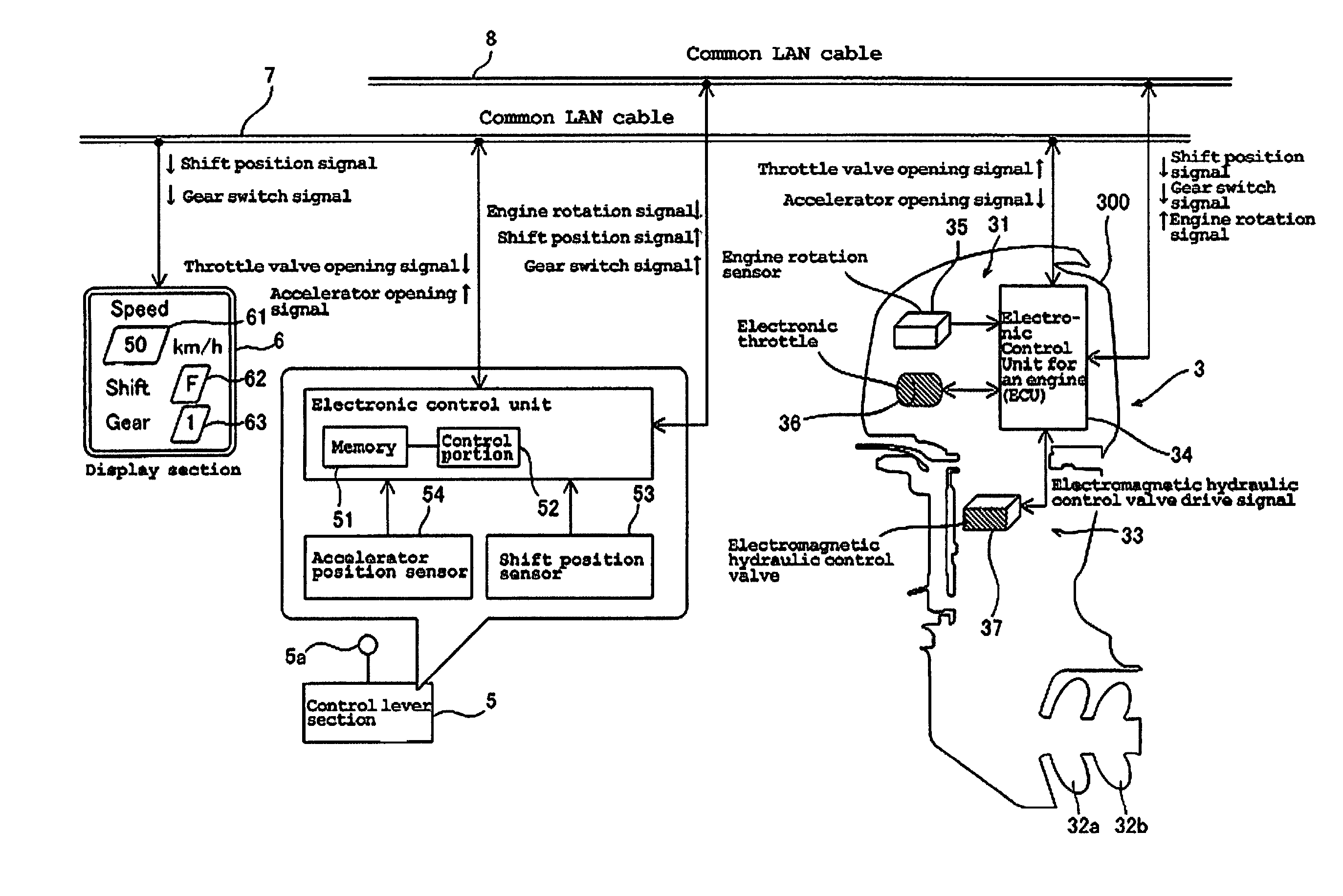
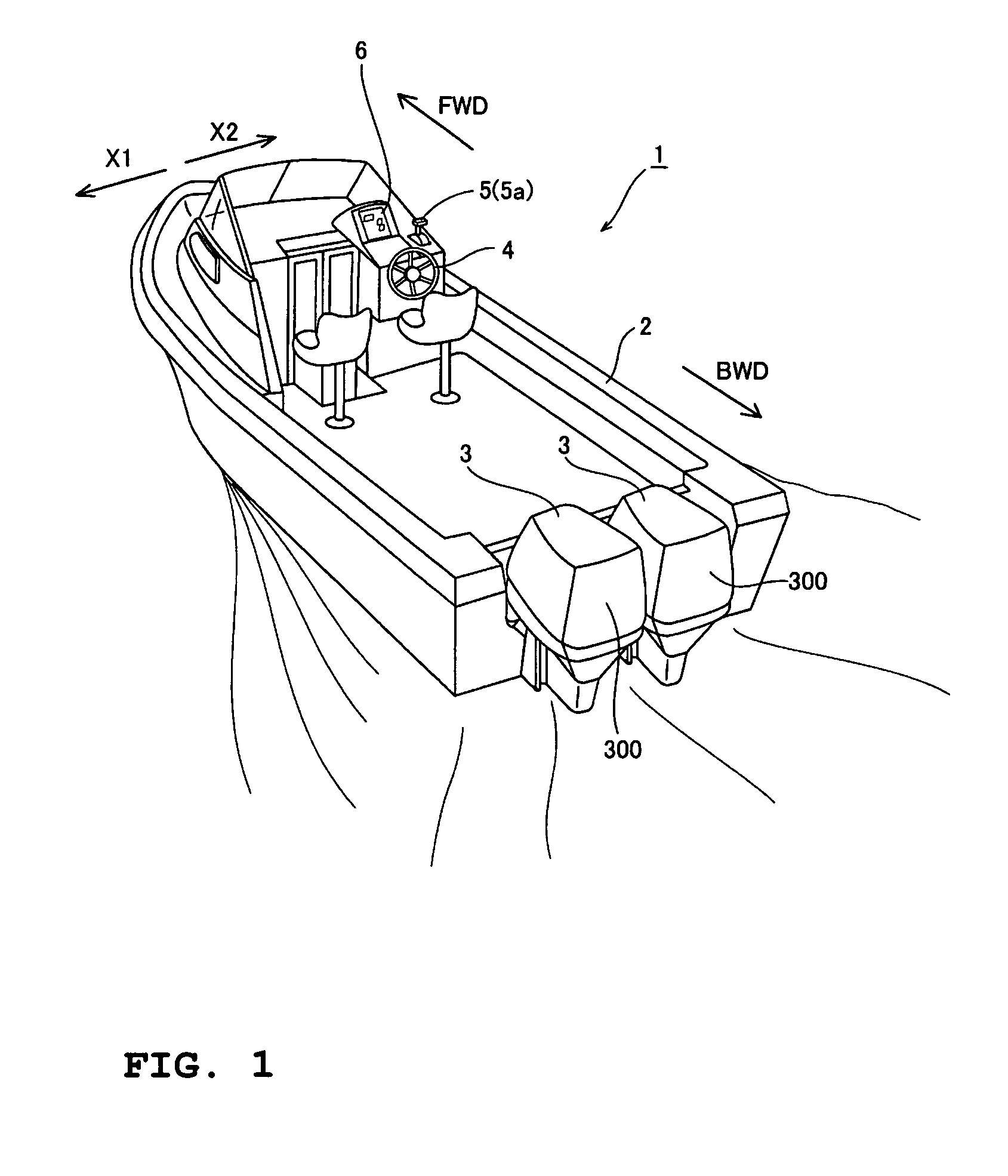
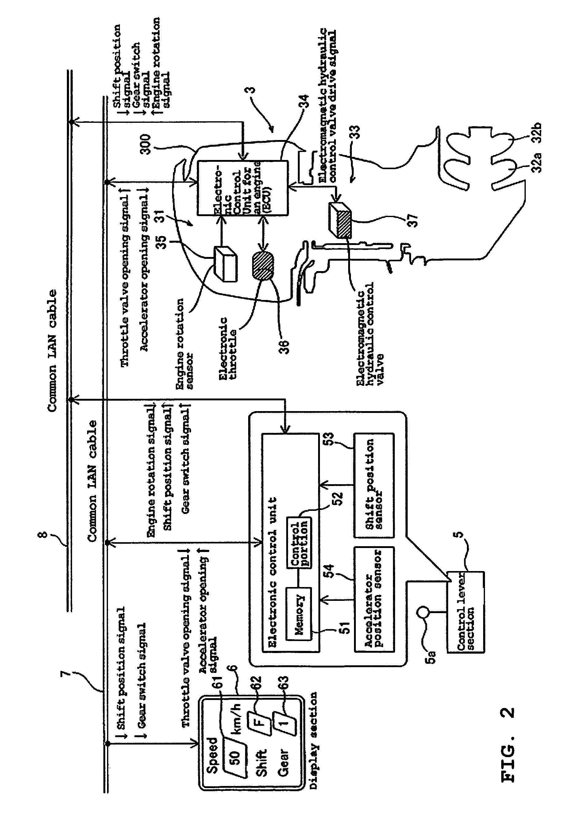
[0024]FIG. 1 is a perspective view of a boat on which a propulsion system for a boat according to a preferred embodiment of the present invention is mounted. FIG. 2 is a block diagram showing the configuration of the propulsion system for a boat according to a preferred embodiment of the present invention. FIGS. 3 to 7 are drawings explaining in detail the configuration of the propulsion system for a boat according to a preferred embodiment of the present invention. In the drawings, FWD indicates a forward direction of the boat, and BWD indicates a backward direction thereof. Referring to FIGS. 1 to 7, a description will now be made of the configuration of a boat 1 according to a preferred embodiment of the present invention and a configuration of the propulsion system for a boat, which is mounted on the boat 1.

[0025]As shown in FIG. 1, the boat 1 according to a preferre...


PUM


Abstract

A propulsion system for a boat includes propellers rotated by an engine, a transmission mechanism arranged to transmit a driving force of the engine to the propellers in a state that the driving force of the engine is changed to at least one of a gear reduction ratio for low speed and a gear reduction ratio for high speed, and a control unit arranged to output a signal to control a gear shift in the transmission mechanism on the basis of a throttle valve opening of the engine and a speed of the engine and arranged to detect cavitation generated in conjunction with rotation of the propellers on the basis of a gear shift control map. The control unit is arranged to control the output of a signal to the transmission mechanism to change the high speed reduction gear ratio when cavitation is detected. The propulsion system achieves both acceleration and maximum speed at performance levels desired by an operator of a boat.

Description

BACKGROUND OF THE INVENTION[0001]1. Field of the Invention[0002]The present invention relates to a propulsion system for a boat, and more particularly relates to a propulsion system for a boat equipped with an engine.[0003]2. Description of the Related Art[0004]Conventionally, a propulsion unit for a boat equipped with an engine (a propulsion system for a boat) has been known (see Patent publication JP-A-Hei 9-263294, for example). Patent publication JP-A-Hei 9-263294 discloses a propulsion unit for a boat equipped with an engine and a power transmission mechanism for transmitting a driving force of the engine to a propeller at a given, fixed gear reduction ratio. This propulsion unit is constructed such that the driving force of the engine is directly transmitted to the propeller through the power transmission mechanism and such that the rotational speed of the propeller increases as the engine speed increases.[0005]However, in the propulsion unit (propulsion system) disclosed in t...

Claims


Application Information

Patent Timeline
Patent Type & Authority Patents(United States)
IPC IPC(8): B63H23/00
CPCB63H21/213B63H23/08B63H23/30
Inventor SUZUKI, TAKAYOSHINAKAMURA, DAISUKE
Owner YAMAHA MOTOR CO LTD
Learn More