
Mass spectrometer

a mass spectrometer and mass spectrometer technology, applied in the field of mass spectrometers, can solve the problems of difficult to design an ion optical system, unavoidable enlargement of the device, and little design freedom, and achieve the effects of stable condition, easy orbit design, and easy positioning

Active Publication Date: 2010-07-27
SHIMADZU CORP +1
View PDF2 Cites 4 Cited by
  • Summary
  • Abstract
  • Description
  • Claims
  • Application Information

AI Technical Summary

Benefits of technology

[0018]The present invention has been achieved in view of the aforementioned problems, and a main objective thereof is to provide a multi-turn time-of-flight mass spectrometer or a Fourier-transformation mass spectrometer wherein design freedom is enhanced while design complications are resolved by making it easy to locate an ion optical system adapted to the conditions concerned.
[0023]On the contrary, according to the ion optical system of the mass spectrometer according to the present invention, a stable condition of a loop orbit is substantially alleviated in comparison with that of the conventional technique, making it easier to locate an ion optical system adapted to the condition, providing easier orbit design and enhancing design freedom, so that an ion optical system adapted to specifications such as an entire device size can be easily provided. The tolerances for the shape and position of the electrodes and other structural dimensions of the ion optical system can be widened without causing a decrease in the performance, which is advantageous to the reduction of manufacturing costs.

Problems solved by technology

However, elongation of a flight distance on a straight line requires unavoidable enlargement of the device, which is not practical, so that a mass spectrometer called a multi-turn time-of-flight mass spectrometer has been developed in order to elongate a flight distance (e.g. refer to Patent Document 1 and Non-Patent Document 1 or other documents).
However, it is extremely difficult to design an ion optical system which satisfies the aforementioned perfect focusing condition required in the conventional multi-turn time-of-flight mass spectrometer.
However, the aforementioned focusing conditions are too strict to locate a physically feasible ion optical system which satisfies the conditions in practice, and since the ion optical systems thereby located have only a small number of variations, there is little design freedom in the present circumstances.
Furthermore, the ion optical system thus located has narrow tolerances for the shape and arrangement of the electrodes and other structural dimensions, wherein the mass resolution, sensitivity and other performance tend to significantly decrease unless the ion optical system is fabricated strictly as designed.
The aforementioned focusing conditions are an ideal condition, and the time-focusing condition expressed by the equations (6) to (8) is relatively easy to satisfy in general but the entire space-focusing condition expressed by the equations (9) to (18) is extremely difficult to satisfy.
However, satisfying the geometrical conditions for creating a double symmetrical structure decreases the number of parameters relating to the components of the ion optical system, thereby design freedom is reduced.
Thus, it cannot be expected that the probability of finding out an appropriate ion optical system as a solution will be higher.

Method used


Image

  • Mass spectrometer
  • Mass spectrometer
  • Mass spectrometer

Examples


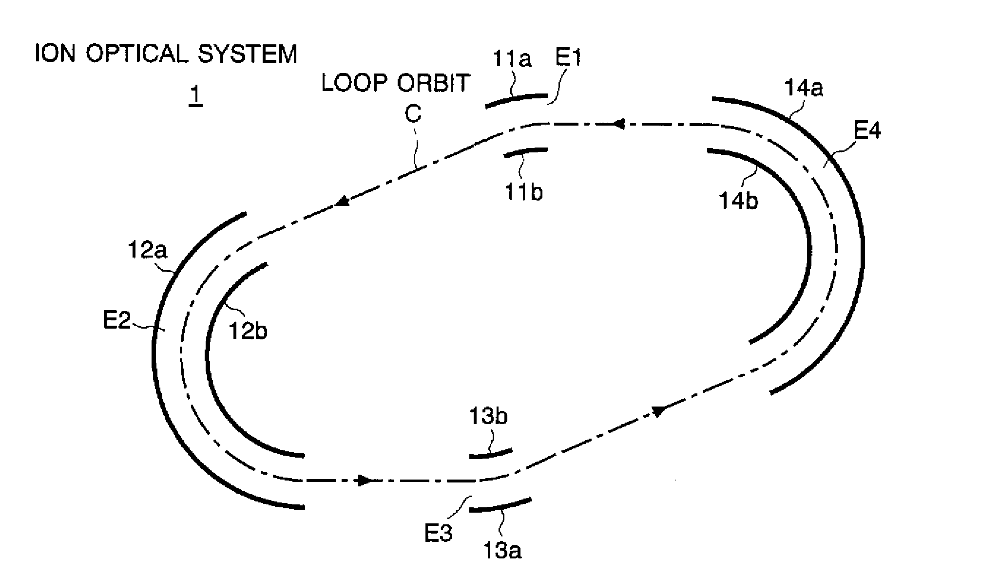
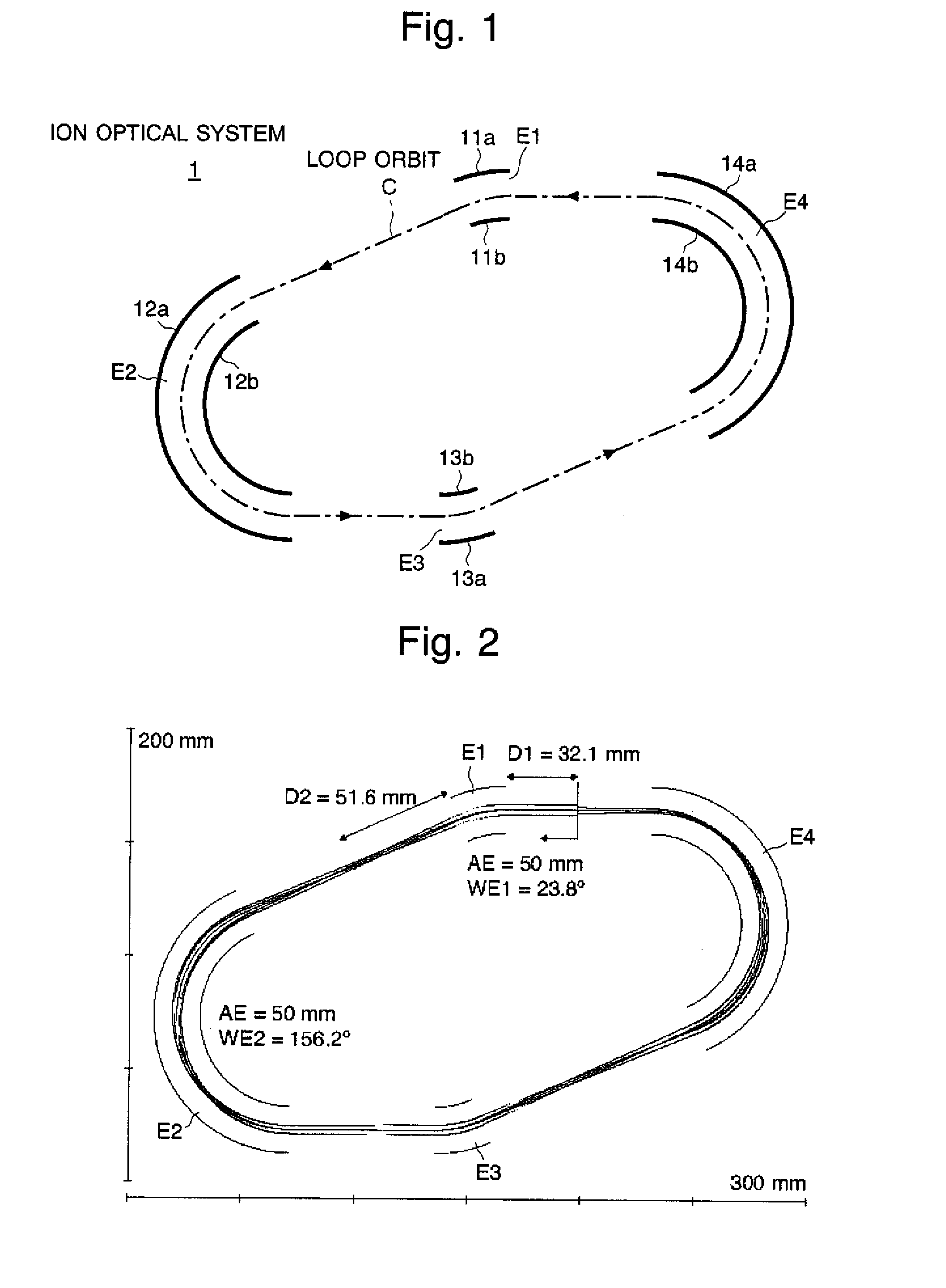
first embodiment

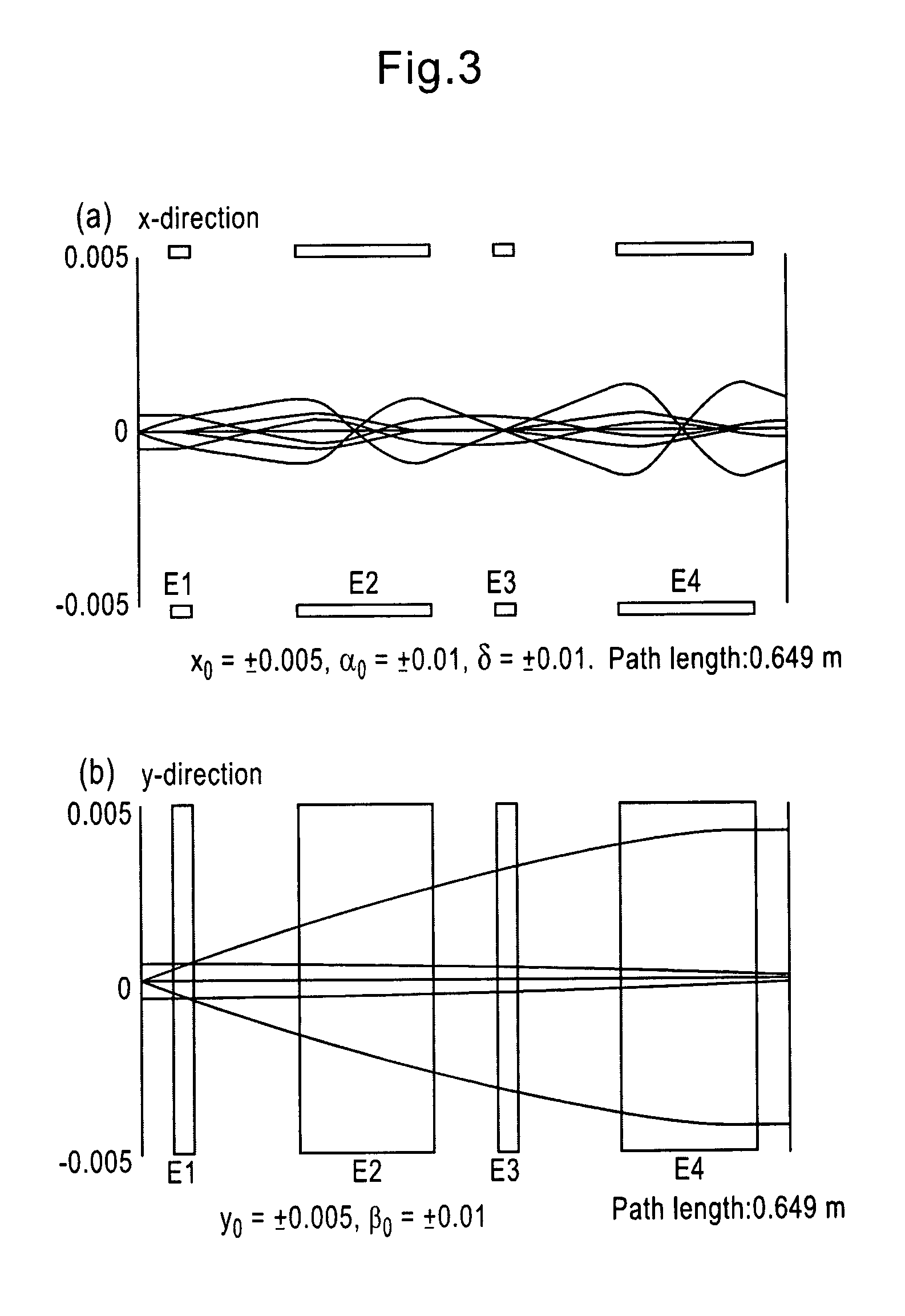
[0036]An explanation will be made for a multi-turn time-of-flight mass spectrometer as one embodiment (i.e. first embodiment) of the present invention referring to the drawings. The ion optical system in the mass spectrometer of the present embodiment was designed so that it satisfies the following equation as the time-focusing condition:

(t|x)=(t|α)=(t|δ)=0  (19)

and satisfies the following equations as the space-focusing condition:

−2x|x)+(α|α)<2  (20)

−2y|y)+(β|β)<2  (21)

[0037]The loop orbit was formed by four of the first to fourth toroidal sector-formed electric fields. To create a geometric structure having double symmetry, the first toroidal sector-formed electric field and the third toroidal sector-formed electric field were made to have the same shape and the second toroidal sector-formed electric field and the fourth toroidal sector-formed electric field are also made to have the same shape. Under these conditions, the parameter settings for each electric field were explored.

[...

second embodiment

[0043]Explained next will be another embodiment (i.e. second embodiment) of the present invention with reference to the drawings. In the present embodiment, the ion optical system 1 explained in the first embodiment is applied to a Fourier-transformation mass spectrometer. FIG. 7 is a schematic top view of the ion optical system 1 in the mass spectrometer of the present embodiment, and FIG. 8 is a view showing one example of a time-of-flight spectrum created in the present device.

[0044]This Fourier-transformation mass spectrometer is provided with a detector 2 of an ion non-destructive type in the middle of the loop orbit C as shown in FIG. 7. This detector 2 outputs an electric signal corresponding to an amount of passing ions, i.e. a kind of electrically charged particles, by using electromagnetic induction or other electrical effects. Now, suppose that ions are made to turn N times along the loop orbit C. In this case, the ion passes through the detector 2 in every cycle of the l...


PUM


Abstract

An ion optical system to form a loop orbit is provided to sufficiently ensure required performance such as ion transmission efficiency while making it easy to design the system by alleviating a space-focusing condition. The loop orbit of the ion optical system is realized so as to satisfy (t|x)=(t|α)=(t|δ)=0 as the time-focusing condition and to satisfy −2<(x|x)+(α|α)<2, and −2<(y|y)+(β|β)<2 as the space-focusing condition. (x|x) and other similar terms are constants determined by the elements indicated in the parenthesis in a general expression format of the ion optical system. The conditions are substantially alleviated as opposed to the conventional space-focusing condition where each of (x|x), (α|α), (y|y) and (β|β) needs to be ±1. Thus, the parameters to decide the shape of electrodes by which the ion optical system is configured have higher degree of freedom.

Description

BACKGROUND OF THE INVENTION[0001]The present invention relates to a mass spectrometer, and more specifically to a multi-turn time-of-flight mass spectrometer or a Fourier-transformation mass spectrometer including an ion optical system in which ions are made to fly repeatedly along a closed loop orbit.[0002]In a time-of-flight mass spectrometer (TOF-MS), the mass of an ion is generally calculated from the time of flight which is obtained by measuring a period of time required for the ion to fly at a fixed distance, on the basis of the fact that an ion accelerated by a fixed energy has a flight speed corresponding to the mass of the ion. Accordingly, elongating the flight distance is particularly effective to enhance the mass resolution. However, elongation of a flight distance on a straight line requires unavoidable enlargement of the device, which is not practical, so that a mass spectrometer called a multi-turn time-of-flight mass spectrometer has been developed in order to elonga...

Claims


Application Information

Patent Timeline
Patent Type & Authority Patents(United States)
IPC IPC(8): H01J49/06
CPCH01J49/408
Inventor NISHIGUCHI, MASARUYAMAGUCHI, SHINICHITOYODA, MICHISATO
Owner SHIMADZU CORP
Learn More