
Air turbine with recycled air or gear mechanism to increase internal velocity for engine power

Active Publication Date: 2010-07-27
DRAVIS MARTIN W
View PDF18 Cites 7 Cited by
  • Summary
  • Abstract
  • Description
  • Claims
  • Application Information

AI Technical Summary

Benefits of technology

[0014]Accordingly, a feature of this invention lies in its use of a gear mechanism to enhance the performance of an air turbine engine.
[0015]Another feature hereof lies in the use of an air recirculation mechanism, alone or in combination with a gear mechanism, to accelerate and compress the air that enters the air turbine engine to increase the efficiency of the engine.

Problems solved by technology

However, such interest has existed for a number of years, but have not yielded significant commercial systems to meet these concerns.
These prior art systems, though offering supplemental propulsion mechanisms for moving vehicles, fail to offer the efficiency needed to effect an alternative and supplemental mechanism for new vehicles and for retrofitting to existing vehicles in the manner of the present invention, nor to provide a mechanism to accelerate and compress the air that enters the air turbine engine.

Method used


Image

  • Air turbine with recycled air or gear mechanism to increase internal velocity for engine power
  • Air turbine with recycled air or gear mechanism to increase internal velocity for engine power
  • Air turbine with recycled air or gear mechanism to increase internal velocity for engine power

Examples


Embodiment Construction

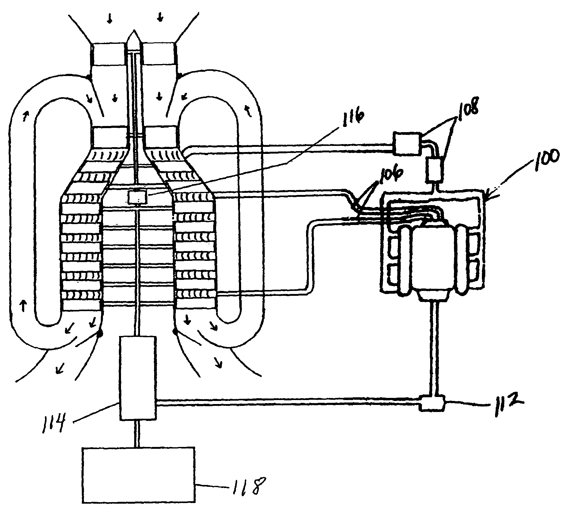
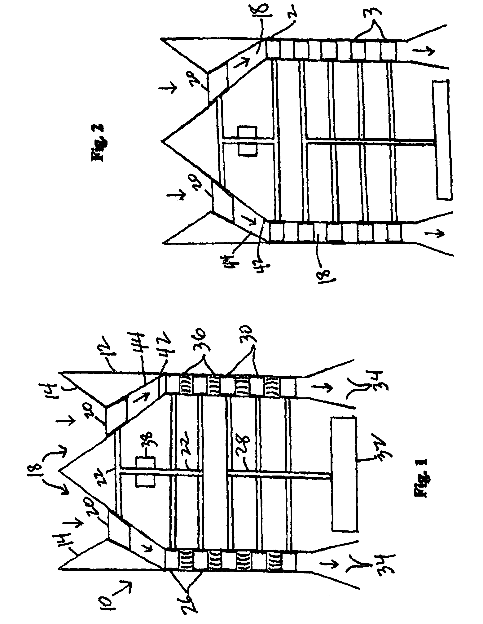
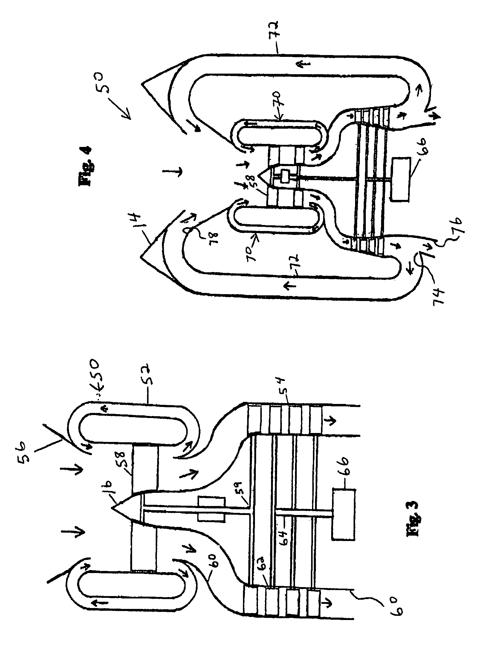
[0021]This invention represents, improvements over the parent application and is directed to two enhancements to increase performance of air turbine engines by accelerating and compressing the air that enters the air turbine engine. A first embodiment or enhancement incorporates a gear mechanism to increase the acceleration and compression. A second embodiment or enhancement lies in the use of an air recirculation mechanism, where the respective enhancements may be employed alone or in combination.

[0022]The system of the parent invention, especially when coupled with the enhancements hereof, is different from a standard jet engine or gas turbine engine in that it will not burn the compressed air. It is also different from other air turbines in that it employs a compressor(s) to actively accelerate and compress the air, where other versions of air turbines do not compress the air or they simply rely on the Bernoulli Effect to passively accelerate and compress the air. The compressors...


PUM


Abstract

An air turbine power propulsion engine for use in powering a vehicle, i.e. automobile or plane, or an electrical generator. The engine is housed in a generally circular housing that features a tapered air intake end and a downstream exhaust end. Within the housing is a generator, first and second drive shafts, and at least one compressor. The at least one compressor is driven by the first drive shaft, while a series of turbine blades drive the second drive shaft which in turn drives the generator. The invention incorporates into the engine a differential gear mechanism to accelerate and compress the air that enters the engine, where the gear mechanism drives the compressor at a higher speed than the turbine blades. A second such mechanism, alone or in combination with the gear mechanism, lies in the use of an air recirculation duct works.

Description

RELATED APPLICATION[0001]This application is a continuation-in-part (CIP) of Ser. No. 11 / 305,864, filed Dec. 19, 2005, by the inventor hereof, where the contents thereof are incorporated herein by reference in its entirety.FIELD OF THE INVENTION[0002]This invention is directed to the field of air turbine engine systems of the type that may be used to power a vehicle, augment the power of a vehicle, and / or drive a generator to produce electricity, more particularly to an engine system that uses multiple turbines, and / or an air recirculation mechanism to effect increased acceleration and compression of the air of the airflow within the engine.BACKGROUND OF THE INVENTION[0003]The present invention relates to a unique air turbine engine system for a moving vehicle, such as an automobile, truck, airplane and the like. As will become clearer hereafter, there are two enhancements of the engine according to the invention, where each enhancement, alone or together, accelerates and compresses...

Claims


Application Information

Patent Timeline
IPC IPC(8): F02B63/04F01D15/10
CPCF01D1/023F01D15/10Y02T50/671F05D2260/40311Y02T50/60
Inventor DRAVIS, MARTIN W.
Owner DRAVIS MARTIN W
Learn More