Intelligent, universal, reconfigurable electromechanical interface for modular systems assembly

a modular system and electromechanical technology, applied in the direction of insulated conductors, cable connections, coupling device connections, etc., can solve the problems of space systems that are heavy, bulky and complex, and achieve the effects of reducing the need for or eliminating, reducing weight, and less complex devices

Inactive Publication Date: 2010-07-27
PHYSICAL SCI
View PDF5 Cites 3 Cited by
  • Summary
  • Abstract
  • Description
  • Claims
  • Application Information

AI Technical Summary

Benefits of technology

[0005]The invention, in one embodiment, features a method and apparatus for forming an electromechanical connection between two or more systems. The connection system can be referred to as AUTOCONNECT (AUTO-configuring electromechanical interCONNECT). In one embodiment, AUTOCONNECT can be used to form electromechanical interfaces in a modular assembly. AUTOCONNECT can be used in any system that requires an electrical connection. Exemplary systems in which an electromechanical connection or an interface (e.g., AUTOCONNECT) can be used include, but are not limited to, computers, radios, televisions, cameras, lighting systems, vehicles, automobiles, spacecraft, and space systems. AUTOCONNECT can reduce the need for or eliminate the need for cables, connectors, mechanical fasteners, and mounting hardware in these, and other, systems. These and other advantages can lead to a significant reduction in weight, less complex devices (no cables to route), reduced integration time and effort (hence lower cost), avoidance of reliability issues associated with cables and connectors, and the flexibility to distribute modules to achieve the desired mass properties.
[0006]An electromechanical connection (e.g., AUTOCONNECT) can be used as an electromechanical fastener that provides mechanical attachment and enables transfer of electrical power, data, and / or signals across mating surfaces of systems. The transfer can occur irrespective of the relative orientation of the two adjoining surfaces. For example, unlike a conventional electrical plug, a first prong need not be pre-designated as a “hot” prong and a second prong as a “neutral” prong. Using AUTOCONNECT, for example, after a plurality of electrical connections is formed, AUTOCONNECT can designate at least one connection to serve as a “hot” connection and at least one connection to serve as a “neutral” connection. More generally, AUTOCONNECT can assign many electrical connections to different functions, such as power, ground, serial data, analog signals, and other similar functions. An advantage of AUTOCONNECT is that precise alignments, angular orientation, and relative positioning of mating systems is not needed in the assembly of systems on the ground or in autonomous assembly of space systems in orbit.
[0007]In one embodiment, an electromechanical interface (e.g., AUTOCONNECT) can be used for assembly of spacecraft on the ground from subsystems and payload modules, resulting in reduction in integration and test time up to an order-of-magnitude compared to current state-of-the art (e.g., several days compared to several months). AUTOCONNECT makes it possible to rapidly assemble, integrate, and test small spacecraft or microsatellites in the field, e.g., to facilitate quick launch of a spacecraft.
[0020]Advantages of an electromechanical connection (e.g., the AUTOCONNECT system) can include a plug-and-play interface that simultaneously provides standardized mechanical and electrical connections between two autonomous modules, e.g., spacecraft subsystems, spacecraft modules, or a spacecraft itself. The electromechanical connection can include intelligence to automatically configure the electrical connections between mating systems using standardized interface software without requiring time-consuming manual pin-out checks and cumbersome documentation. The electromechanical connection can be universal allowing for electromechanical integration without regard to the relative orientation and location of an attaching module relative to a spacecraft deck and / or pane. The electromechanical connection can incorporate numerous redundant electrical connections and continuously checks for the presence of “good” contacts, making the system inherently robust by discarding faulty connections and reconfiguring their functions using good connections.
[0021]Some advantages of AUTOCONNECT for spacecraft subsystems and payload modules include that AUTOCONNECT-covered surfaces can be rapidly assembled onto spacecraft decks or panels also equipped with AUTOCONNECT on their surfaces, while simultaneously keeping within spacecraft mass constraints. Any subsystem or payload module can be mounted anywhere on a spacecraft panel. Furthermore, modules can be mounted interchangeably. A sensor or subsystem specific to a particular space mission can be assembled in the field within minutes. AUTOCONNECT provides functional reconfigurability and mission-adaptive flexibility. AUTOCONNECT's reconfigurability yields a high level of robustness and reliability of electrical connections as a spacecraft encounters thermal cycles and inertial forces on-orbit.
[0022]An electromechanical connection can be formed without the need for cables and / or connectors. Furthermore, AUTOCONNECT can provide secure and robust mechanical attachment between spacecraft decks and panel modules and / or subsystem and payload modules without the need for mounting brackets and hardware. The reduction or elimination of mounting hardware, cables and harnesses, and electrical connectors and strain reliefs can achieve approximately 15% mass savings for a spacecraft system. A significant volume savings is achieved as “dead zones” that result from bulky electrical connectors and strain reliefs around subsystem and payload boxes can be reduced or eliminated. For example, an approximately 15% volume reduction can be achieved. Further, a significantly simpler spacecraft assembly process with reduced complexity and greater reliability is achieved. The reduction or elimination of the need for manual electrical / mechanical checkouts and associated interface documentation during assembly can mean significantly simpler and / or faster spacecraft integration and test processes requiring less labor and resulting in substantial cost savings. An estimated factor of 10 reduction in the time needed to assemble and / or integrate a spacecraft can be realized.

Problems solved by technology

This results in space systems that are heavy, bulky and complex.

Method used


Image

  • Intelligent, universal, reconfigurable electromechanical interface for modular systems assembly
  • Intelligent, universal, reconfigurable electromechanical interface for modular systems assembly
  • Intelligent, universal, reconfigurable electromechanical interface for modular systems assembly

Examples


Embodiment Construction

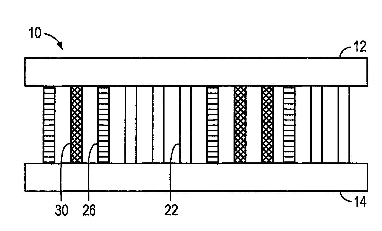
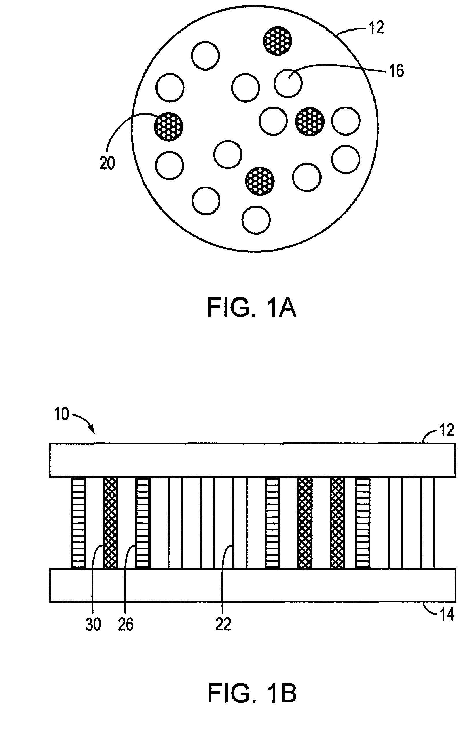
[0051]FIG. 1A shows a first substrate 12 for forming a reconfigurable electromechanical connection. The first substrate 12 includes a non-conductive array of elements 16 and one or more conductive regions 20. FIG. 1B shows a cross sectional view of reconfigurable electromechanical connection interface 10 between a first substrate 12 and a second substrate 14. The first substrate 12 and / or the second substrate 14 can take a variety of shapes. Suitable shapes include but are not limited to a square, circle, polygon, triangle, parallelogram, quadrilateral, hexagon, or octagon.

[0052]When the first substrate 12 and the second substrate 14 are mated, non-conductive array of elements 16 and conductive regions 20 can overlap. If a non-conductive array of element 16 of the first substrate 12 overlaps with a non-conductive array of the second substrate 14, a non-conductive connection 22 is formed. If a non-conductive array of element 16 of the first substrate 12 (or the second substrate 14) o...


PUM

PropertyMeasurementUnit
temperatureaaaaaaaaaa
temperaturesaaaaaaaaaa

Abstract

An electromechanical connection includes a first conductor disposed in a first non-conductive array and a second conductor disposed in a second non-conductive array capable of mating with the first non-conductive array. The second conductor is capable of mating with the first conductor when the first non-conductive array and the second non-conductive array are mated. A processor associated with the first non-conductive array determines if an electrical connection is formed between the first conductor and the second conductor. The processor can assign a function to the electrical connection.

Description

CROSS REFERENCE TO RELATED APPLICATION[0001]This application claims the benefit of and priority to U.S. Provisional Patent Application No. 60 / 919,302, filed Mar. 21, 2007, the entire disclosure of which is incorporated herein by reference.GOVERNMENT RIGHTS[0002]The invention was made with funding provided by the National Aeronautics and Space Administration, contract number NNM05AA12C. The federal government may have rights in the invention.FIELD OF THE INVENTION[0003]The invention relates generally to a method and apparatus for forming an electromechanical interface for a modular assembly. In one embodiment, the invention relates to an electromechanical interface for a modular assembly of electronic systems.BACKGROUND OF THE INVENTION[0004]Electrical and mechanical connections between systems can require bulky cables and mounting hardware to ensure reliable connectivity. The cables and hardware can add weight to a device and use valuable space, which can otherwise be eliminated mak...

Claims


Application Information

Patent Timeline
Patent Type & Authority Patents(United States)
IPC IPC(8): H01B7/30H01B11/02H02G5/06H02B1/20
CPCH01R29/00
Inventor JOSHI, PRAKASH B.DECKER, BRIAN K.MAGILL, JOHN C.HINDS, MICHAEL F.
Owner PHYSICAL SCI
Why Eureka
Try Eureka